In an old active three way loudspeaker of a friend one of the TDA7294 has firmly blown a hole in itself. No apparent cause. After cleaning the board from black dust, the surrounding standard components on the standard pcb layout measure fine. The mute is not used. The loudspeaker unit of this mid channel measures ok.
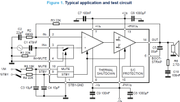
After replacing the TDA7294, an offset of 0,4Vdc appears (input shorted). It can be traced back to the IN- by measuring the voltage at that input in relation to ground.
Without power supply R3 = 22k measures fine.
The other two TDA7294 on the pcb of this loudspeaker measure fine, hardly any offset at the output.
The voltages of the power supply are a stable + / - 25Vdc. The scope shows no sign of oscillation.
What may cause the offset of 0.4V ?
Attachments
Last edited:
On the positive input no voltage to be measured. I have measured all components, including R1 and C1, with a Hameg component tester. The resistors were with measured with a BM869s multimeter. No odd outcomes.
When replacing the chipamp, all traces on the pcb were checked for shorts and cleaned from flux residues. The layout is the same for all three amps.
When replacing the chipamp, all traces on the pcb were checked for shorts and cleaned from flux residues. The layout is the same for all three amps.
Last edited:

The new TDA9472 being bad is indeed an option. A bunch of them were ordered in order to have some spares at a reliable source, Reichelt in Germany.
Before putting in a new chip. just changing the external components may be interesting. R3 = 22k can measure ok without power on, but the resistor can be stressed when the chip blew. If so, it may show odd behaviour under power. When under power now, a voltage of 20 mV across R3 can be measured.
Would it yield additional information when simply removing R3, and have no feedback.
But, will the TDA7294 be stable without R3?
TDA7293 and TDA7294 have a reputation to suddenly blow up. Replaced quite a few of these in the past in Linn amplifiers and vowed never to use these myself 🙂 I forgot why but I recall that after a certain date a revision was done to prevent it. It is IN the IC just like with TDA7265 that also likes to explode. In cases I have had rectifier diodes that shorted out because of the TDA becoming a short circuit also taking away a PSU cap that are usually not fond of AC. TDA7297 is also one of them unfortunately. The originals don't take issue with 16V but the copies go BOOM.
As often unreliable stuff becomes very popular (sounds best!!!! DMOS!!!) but then one has to deal with this error possibility. It does not help that chinese copies exist that look exactly like the originals which are as said also a lottery.
Anyway it is in the TDA7293/94 case advisable to add loudspeaker protection.
Edit: I think it has to do with the standby and mute pins. Could be wrong though.
Last edited:
The following thread mentions in post 882 currently at least five variants of the TDA7294 are on the market, each with a different purpose and different specs.
https://www.diyaudio.com/community/threads/optimizing-tda7294-output.226437/page-45#post-5713236,
Oh well: first to be checked now is what gardenvariety was delivered in the order.
To make it even more simple, for new production the datasheet of the TDA7296 seems applicable, instead of the one for TDA7294.
Last edited:
I know it's a post from last month.In an old active three way loudspeaker of a friend one of the TDA7294 has firmly blown a hole in itself. No apparent cause. After cleaning the board from black dust, the surrounding standard components on the standard pcb layout measure fine. The mute is not used. The loudspeaker unit of this mid channel measures ok.
After replacing the TDA7294, an offset of 0,4Vdc appears (input shorted). It can be traced back to the IN- by measuring the voltage at that input in relation to ground.
Without power supply R3 = 22k measures fine.
The other two TDA7294 on the pcb of this loudspeaker measure fine, hardly any offset at the output.
The voltages of the power supply are a stable + / - 25Vdc. The scope shows no sign of oscillation.
What may cause the offset of 0.4V ?
I had same issue with some TDA72XX. Where I live there is no cheap way of making sure the TDA is original and I had the high offset issue in some new and replacements I did for my self.
Similar offsets of 300mV, 400mV etc.
I added 2 resistors from a DC filtered source in the + input so as to insert a small DC bias and I could bring down the output offset to something acceptable. Just take the DC output value divide it by the voltage gain and you'll get the oposite DC signal to be inserted in the inputs to compensate.
Thanks for thinking along by sharing your viable solution. It may be the simplest way to solve the issue, as again removing the chip is not beneficial for the pcb traces. Even with using low temp chip quik solder. In first instance, a trim pot will come handy to find the right value in a voltage divider.
TDA7293/94 usually blows out when the voltage on pin 8 is much lower than that on pin 15. Sometimes just switching on/off the psu may cause that. If you design carefully it would never happen though.
If this happens the bootstrap capacitor may get damaged.
I always buy TDA7293/94 from Mouser and after many hundreds used I've never seen this power chip blowing out in my designs.
If this happens the bootstrap capacitor may get damaged.
I always buy TDA7293/94 from Mouser and after many hundreds used I've never seen this power chip blowing out in my designs.
Last edited:
Buying from Mouser is my dream! 🙂
They do ship to here, but the total cost is insane. Example: TDA7293 cost US$8.36. The shipping cost 35.00 flat, so total of 43.36. On top of that we have import tax of 60% and state tax 18% (calculated by inside). So, 43.36*1.6/0.82 = 84.60 for a TDA7293.
On the other hand, if I buy from local shops online, I pay only 7.24 - but who knows from where this IC comes from and if they are original or not.
For people interested in tda7293:
https://www.futureelectronics.com/p...nt=instock&utm_campaign=Octopart_Ext_Referals
Don't miss this very nice deal.
https://www.futureelectronics.com/p...nt=instock&utm_campaign=Octopart_Ext_Referals
Don't miss this very nice deal.
Attachments
I'm hoping this thread is still live as I also have a TDA7294 DC offset issue.
The 7294 chips are from CPC so I assume they are not counterfeit. I've soldered them on identical Ali express sourced pcb's using identical components. They are for a three way active stereo system, so 6 amps in all. I use loudspeaker protection circuits (Project 33 boards from Rod Elliott in Australia) that only connect each speaker through a relay when there is no DC detected at the amp output. Tested, all 6 amps have the correct quiescent current and do not overheat. Connected direct to a test speaker they all sound fine. However I discovered that three of them trip the loudspeaker protection relay when connected to that. Further investigation showed these amps creating a DC offset at the speaker output of between 1.5 and 4.0 volts with no load, compared to about 50mV for the three 'good' amps.
I have double checked wiring, solder bridges dry joints etc etc and all the boards are fine.
My thinking is that the amps that show a DC offset with no load may be oscillating, and that this is showing up as a dc offset on my cheapo multimeter. However, they do not get unduly hot when used with my test loudspeaker.
I'm stumped. I'm reluctant to use the amps without the protection circuit. Is there something else I could try?
Just recently, I replaced the bootstrap capacitor (after removing it measured ok, but see post 10), and soldered in a TDA7293. All fine now. Thanks to all who responded.
How is it possible that the measurement of the capacitor is good and it caused problems?Just recently, I replaced the bootstrap capacitor (after removing it measured ok, but see post 10), and soldered in a TDA7293. All fine now. Thanks to all who responded.
The capacitor was only replaced as precaution. Apparently, that was not the problem. Or maybe the capacitor was damaged back then when the chipsamp exploded, and may start malfunctioning when put under dc-voltage.
Or maybe the offset was caused by a faulty chipsamp (although ordered from a trustworthy firm).
I do not look back, I am afraid.
Or maybe the offset was caused by a faulty chipsamp (although ordered from a trustworthy firm).
I do not look back, I am afraid.
That’s what has me stumped. My guess is that what appears as dc offset to my meter and to the protection circuit is not that but some kind of oscillation above audio frequency (I dont have a ‘scope to check). Connected directly to a yeast speaker all 6 amps sound perfect.@JMacI: under no load, there should not be any serious dc-offset. Maybe you can connect another speaker unit to the faulty chipsamp to rule out this is of influence.
- Home
- Amplifiers
- Chip Amps
- TDA7294 offset issue