Later in the afternoon I'll send it. Today my doughter got my camera for new year's party 🙂 . Anyway , Happ New year to all audiophiles in this forum.
Stefano
Stefano
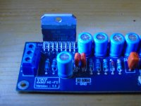
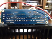
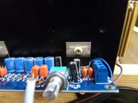
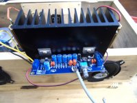
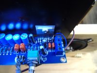
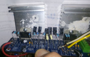
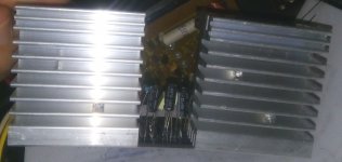
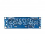
Here I send some picture of the poor amp. I show the board after mounting components , the connection to heatsink , the all together view , and my trial to disconnect the Vss pins from the IC2 .
this is the Ist part , the IInd follows
this is the Ist part , the IInd follows
Attachments

Second part of the message
Ok , this is my last trial , then I think I try to remove all and mount on another board. I suspect I did a really dum operation , but everything is dum once you discover it , not before.
bye
Stefano
Ok , this is my last trial , then I think I try to remove all and mount on another board. I suspect I did a really dum operation , but everything is dum once you discover it , not before.
bye
Stefano
Attachments
I have reported on two different XY 3886 PCBs.
Both have small errors in the grounding layout.
Is the XY 7293 just as good, or worse than the small errors in the 3886?
Both have small errors in the grounding layout.
Is the XY 7293 just as good, or worse than the small errors in the 3886?
I don't have any LM3886 board to chek. Anyhow i'll try to see with tester.
PS: do you think that missing the bypass capacitor on pin 13 during my test could cause an overcurrent ? For RF autooscillating I mean ?? SInce during my test , i tied up the VSS+ connected pins , and in this way , when i supply it , there is no capacitor conneted.
best regards
PS: do you think that missing the bypass capacitor on pin 13 during my test could cause an overcurrent ? For RF autooscillating I mean ?? SInce during my test , i tied up the VSS+ connected pins , and in this way , when i supply it , there is no capacitor conneted.
best regards
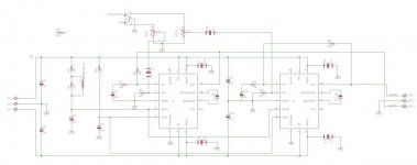
Sorry to interfere after 4 years. Does anyone have the values of the parts and schematic for the PCB @barbonist has used? I bought the same PCB from ebay, but the vendor has not sent the documentation.
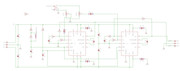
The drawing in post #19 seems to have component designators and values. You may have to open it in a new window to see full size.
Thank you very much. I have two questions:
1. What value is the potmeter at the input?
2. Why is R7 represented outside the schematic?
1. What value is the potmeter at the input?
2. Why is R7 represented outside the schematic?
I have planted the parts on the stereo board. The sound is good on 8Ohm, although i suspect the power is lower than 100W. I think the IC's get quite hot at medium volume.

1. The power supply is symmetrical 2 x 26v. I have measured the voltages on the capacitors. I think something might not be in order.
C1,C7 - 15v;
C5, C9 - 26v;
C6, 10 - no voltage ?! ;
C8, C13 - 19v.
What other voltages should i measure in order to pinpoint the problem?
The terminals of the parts are long because i planted them for a test. I plan to use tantalum capacitors and better quality resistors. The terminals don't touch, although they might look like touching.
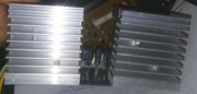
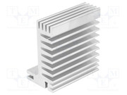
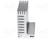
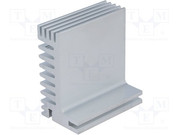
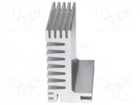
2. The radiator is L shape, SK610 from Fischer. PDF in the attachment
SK 610 50 AL FISCHER ELEKTRONIK - Heatsink: extruded SK610-50AL | TME - Electronic components
Dimensions: 50mm x 55mm x 31mm
Is it enough?
3. I did not have 1uF capacitorsfor input C11, C12. I put 220nF. How does this affect the sound or the performance?
1. The power supply is symmetrical 2 x 26v. I have measured the voltages on the capacitors. I think something might not be in order.
C1,C7 - 15v;
C5, C9 - 26v;
C6, 10 - no voltage ?! ;
C8, C13 - 19v.
What other voltages should i measure in order to pinpoint the problem?
The terminals of the parts are long because i planted them for a test. I plan to use tantalum capacitors and better quality resistors. The terminals don't touch, although they might look like touching.
2. The radiator is L shape, SK610 from Fischer. PDF in the attachment
SK 610 50 AL FISCHER ELEKTRONIK - Heatsink: extruded SK610-50AL | TME - Electronic components
Dimensions: 50mm x 55mm x 31mm
Is it enough?
3. I did not have 1uF capacitorsfor input C11, C12. I put 220nF. How does this affect the sound or the performance?
Attachments
-
SK610.pdf38.9 KB · Views: 67
-
tda7293.pdf391.9 KB · Views: 114
-
 338676.jpg27.4 KB · Views: 54
 -
 prime_presentation_pres_0003.jpg19.4 KB · Views: 50
 -
 prime_presentation_pres_0004.jpg19.9 KB · Views: 53
 -
 IMG_20190816_193036.jpg174.7 KB · Views: 50
 -
 IMG_20190816_193234.jpg539.9 KB · Views: 67
 -
 61fNbLUTAGL._SL1024_.jpg78.1 KB · Views: 61
 -
 amp002.jpg63.5 KB · Views: 76
- Status
- Not open for further replies.
- Home
- Amplifiers
- Chip Amps
- tda7293 power amp