Hi all
I got on ebay a stereo amp with TDA7293 and mounted it.
http://www.ebay.com/itm/New-TDA7293-Amp ... 0701689182
SInce in my first trials i burned both TDA because i inverted + and - , i replaced it and now i supply current via a couple of 100Ohm 15W resistors.
At the beginning all worked fine for 10 minutes , then , suddenly , one TDA is drawing more than 350mA , causing the circuit stop working . Normally , in quiescent mode , the voltage fall on the R was just 5 Volts ( 50 mA ) . I cannot find a reason why TDA could have burned with limiting resistors or could have chenged operating mode.
The power supply is a 38 + 38 V Dc . if you have any idea , it is welcome.

Stefano
I got on ebay a stereo amp with TDA7293 and mounted it.
http://www.ebay.com/itm/New-TDA7293-Amp ... 0701689182
SInce in my first trials i burned both TDA because i inverted + and - , i replaced it and now i supply current via a couple of 100Ohm 15W resistors.
At the beginning all worked fine for 10 minutes , then , suddenly , one TDA is drawing more than 350mA , causing the circuit stop working . Normally , in quiescent mode , the voltage fall on the R was just 5 Volts ( 50 mA ) . I cannot find a reason why TDA could have burned with limiting resistors or could have chenged operating mode.
The power supply is a 38 + 38 V Dc . if you have any idea , it is welcome.
Stefano
Have you got the TDA's mounted on a good heatsink ?
Yes Mooly , I mounted it on heatsink with the provided insulator foils and a couple of insulating washers for the screws. I also wonder if it is right to limit current with 2 100ohm resistors , but since i burned the first couple of tda ( 5 euros each ) , i thought this is a good idea since i don't own a good power supply with current limit for my home lab.
Stefano
I would probably suggest a "bulb limiter" rather than series resistors tbh. The bulb limiter is just a 60 watt mains filament bulb in series with the PRIMARY of the mains transformer.
Do the chips get hot while its just powered on and with no audio playing ? They shouldn't.
Any limiting (bulb or resistors) will cause the supply to vary under load, the 100 ohms drastically. That could cause the IC to latch up but I'm surprised if that happened and it was destructive having such high limiting resistors.
The other unknown is how well developed the circuit is. There can be a lot of difference between lifting a circuit from an application note or data sheet and developing a 100% reliable circuit for real world use. So that's an unknown.
Thanks Mooly . Do you have any idea about this bulb ? is it a kind of lamp ? DO you have a link to show me what you mean ? I have 38 + 38 V at the power supply output , but this component should withstand up to 50V + 50V . Since the turn rate of the transformer is 220/32 , 60W lamp should be ok ? Next time i send you my reverse engineered schematics (chinese don't provide it , just mount instructions ).
bye
Stefano
bye
Stefano
The bulb is an ordinary mains 240vac filament household bulb. You wire it series with the live mains to the transformer. Normally the amp draws little current and the bulb is out. If there is a fault, the current rises and the filament resistance increases rapidly limiting the current to the whole amplifier. The bulb is lit under those conditions.
")
Ok , tomorrow i try , then if everythink will roast , i'll send you the roasted tda with some ketchup on top
bye
Stefano
TOday i tried with an external 60W bulb in series with the primary of the transformer. Without signal the bulb glows visibly . Inside one of the 4 ohm speakers , i listen a noise as a kind of whistle mixed to buzz. Is there something strange in the schematics in your opinion ? At the output it is directly connected to the speaker without capacitor.
stefano b
How to attach an image or files,
To add a photo, files or non standard files.
First click "go advanced" in the box below the "quick reply" message box. Doesn't matter if you decide half way through a message to do that, it carries it forward.
Then click "Manage attachements". Maximise the new Window so that you can see all the text.
Click browse in the first box at the top and find your picture. Repeat for any more pictures.
Click upload... a message appears "uploading"
When complete the files will show as being attached. Now click the small text that says "close this window"
The pictures should now be attached and when you submit your post they will appear.
Make sure your pics aren't too big, a couple of 100k is plenty, and many members object when they are massive and it alters the margins
It tells you in the attachments window what max sizes are allowed.
If you want to attach a file that has a non standard format for example excel, circuit simulation etc then try putting the files in a zipped folder and attaching that.
reverse engineered schematics ( only one channel )
the attached schematics is the reverse enginneered schematics from the XY hifi company. I did it with eagle.
do you find something possibly causing strange behaviour ? Maybe +38 and -38 are too much ? or some value cause RF oscillation ?
bye
Stefano
the attached schematics is the reverse enginneered schematics from the XY hifi company. I did it with eagle.
do you find something possibly causing strange behaviour ? Maybe +38 and -38 are too much ? or some value cause RF oscillation ?
bye
Stefano
Attachments
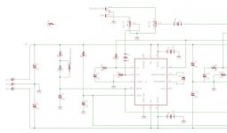
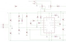
I think the designer decided to connect the +Vs supply to the mute/stdby inputs as on page 6 of 21 of the ST manual. Maybe the timing is a little bit different ? Or maybe there should be a specific slope of the power supply to make this circuit work fine.
http://www.st.com/web/en/resource/technical/document/datasheet/CD00001887.pdf
afaik , the mute time constant during power up should be 40ms for mute and 20ms for stdby . But in my circuit it is a double value. In other words , first the stdby signal reach Vs+ , and after some time the mute signal reach Vs+ too . But my circuit is simply slower to do this. GND is a reference track on the PCB i got , but i draw it as a GND signal. DO you have experience with this chip ?
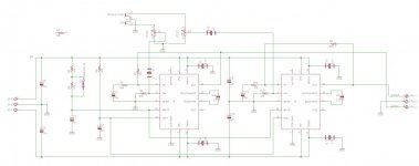
I have shown just one of the 2 chips , I have one input coming from the pot R11/1 going to C11 with R2 polarization , the other input , going to the other chip exactly in the same way , starts from R11/2 and is simply not shown. Ok . I''ll send the whoole diagram in the afternoon.
bye
Stefano
bye
Stefano
- Status
- This old topic is closed. If you want to reopen this topic, contact a moderator using the "Report Post" button.
- Home
- Amplifiers
- Chip Amps
- tda7293 power amp