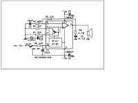
I've build the suggested schematic on pdf file of datasheet.
But i've the following trouble...
1) Turn on my PSU +/-24V
2) All wire connected (input/output)
The trouble is here...
I give +5v at pin3 and for a second it seems to give the right power to the speaker and immediactly after it goes at lower volume with a little tendency to give high frequency as output...
I hope to have be clear....
Some suggestions?
Make sure c3 is connected properly(double check the polarity) and connected to Neg rail supply not ground.
MaXiZ said:Are the red polarity correct?
Yes
MaXiZ said:And if it's alway connected to negative it's always in stand by....
Do you have (-) of C3 connected to neg rail supply?
What is the voltage of your transformer? You may have to lower the supply voltage.
absolutely yes! 🙂Do you have (-) of C3 connected to neg rail supply?
THe original output is around +/-40v but with this (http://sound.westhost.com/project102.htm) i take it down to exactly +/v24..What is the voltage of your transformer?
It is likely to be something simple. Lets start eliminating possible problems.
1 make sure all cap are connected properly(polarity)
2 check all ground wiring
3 measure resistance at pins(between pin and ground)
4 C1 bewteen R1 and pin 7(not R1 and ground)
5 measure at pins 5and 7 : bewteen pins 1 and 6 and bewteen 1 and the (+) of C2
1 make sure all cap are connected properly(polarity)
2 check all ground wiring
3 measure resistance at pins(between pin and ground)
4 C1 bewteen R1 and pin 7(not R1 and ground)
5 measure at pins 5and 7 : bewteen pins 1 and 6 and bewteen 1 and the (+) of C2

Excuse me..
But pin 2 should be connected directly to +V and pin 3 is for play/stand by (by a 22k resistor) and when i want PLAY i make a short to +v right?
But pin 2 should be connected directly to +V and pin 3 is for play/stand by (by a 22k resistor) and when i want PLAY i make a short to +v right?
Dont connected any. Only check the resistance bewteen the pins,You know what the resistance should be.
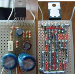
I looked at the picture you posted everything seem OK. The only thing I see that maybe a fault is a possible connection bewteen pin2 and 3(look inside the square).
Have you built more than one?.
You make just have a bad chip. It happens.
Were is the +5V for pin 3 coming from?
I looked at the picture you posted everything seem OK. The only thing I see that maybe a fault is a possible connection bewteen pin2 and 3(look inside the square).
Have you built more than one?.
You make just have a bad chip. It happens.
Were is the +5V for pin 3 coming from?
jaudio said:
Have you built more than one?.
You make just have a bad chip. It happens.
I will go over the schematic and pictures again. I may have missed something.
MaXiZ said:Or i'll try to build some p3a with right output transistor
What is p3a?
just make shure you have the fuse holders on hand..
how damn irritating to have the amp done and those damn fuses missing..
how damn irritating to have the amp done and those damn fuses missing..
- Status
- Not open for further replies.
- Home
- Amplifiers
- Chip Amps
- tda2052