Hi, i'm relatively new here and to amp building. So i made an amp with tda2009a chip according to this diagram on a breadboard.
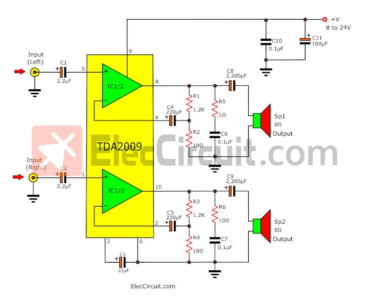
Except i replaced R1,R3 with 10k, and R2,R4 with 1k.
All is well and good at normal volume, but when the volume is turned low , or playing a quiet part of the song, there is noticable distortion. Idk what's it called, but it sounds alot like what happens when you tune a radio channel slightly off.
Lowering the gain by increasing R2,R4 to 4.7k lowers the distortion, likewise decreasing the resistors down to 500, 330, etc increases the distortion.
The chip, input, and power are all grounded at one point, with the grounds from each channel also grounded on either side of that point.
After fiddling around i found that it appears to be the fact that there are two channels. if i disconnect one channel the distortion disappears. Im guessing it's a ground loop; one channel is interfering with the other through R2,R4.
It's been giving me a headache for a while. Does anyone know of a solution to this? thanks much.
Except i replaced R1,R3 with 10k, and R2,R4 with 1k.
What was your reason for doing this? If you look at the DS, page9 has application suggestions and mentions that the closed loop gain should not be below 26dB. Since your choice of resistors gives a value below this recommended minimum, you might have oscillation
As mjf has noted, the schematic shown in the original post shows different values in the output zobel circuits for each channel. The two channels should have the same component values. Use the values shown for the left channel for both.
What type of breadboard are you using? The solderless breadboards that you poke wires into can be problematic. A photo showing what you have so far could be helpful in diagnosing the issue.
One last thought, I've found it best, initially, to stick with the application circuits shown in the product datasheet when working with a new component. Don't change the component values unless you know exactly what you're doing and why you're doing it.
Here is a link to the TDA2009A datasheet:
http://www.st.com/content/ccc/resou...df/jcr:content/translations/en.CD00000127.pdf
yup, needs more gain and a 330pf cap from pn 5 to ground and a notherone from pin1.
that will kill radio pickup for sure.
that will kill radio pickup for sure.
Oops, I guess that one's a bad diagram. the zobel resisters are typo'ed. I do have 1ohm resistors for both.
I actually followed a different diagram, which I can no longer find. But its similar to the one that's in the tda2009 datasheet:

only with 3.3uf input caps and 36ohm instead of 18ohm gain resistors.
I'm pretty sure radio pickup is not the problem though. I forgot to mention the distortion only happens on super low volume. If there's absolutely nothing playing, there is zero noise, which I'm pretty satisfied with. Plus if i completely disconnect one channel all distortion goes away entirely.
I didnt have the exact values resistors, but when I tried with a 1.8k and 64ohm the distortion was super bad, clearly audible on regular volume.
I will now try to find some closer value resistors and try again.
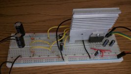
in the meantime I attached a picture of my setup. Note I just added a big heatsink, and spread out the components. But before I had them nice and compact. There was no noticable difference though.
btw I appreciate the feedback guys! 😀
I actually followed a different diagram, which I can no longer find. But its similar to the one that's in the tda2009 datasheet:
only with 3.3uf input caps and 36ohm instead of 18ohm gain resistors.
I'm pretty sure radio pickup is not the problem though. I forgot to mention the distortion only happens on super low volume. If there's absolutely nothing playing, there is zero noise, which I'm pretty satisfied with. Plus if i completely disconnect one channel all distortion goes away entirely.
I didnt have the exact values resistors, but when I tried with a 1.8k and 64ohm the distortion was super bad, clearly audible on regular volume.
I will now try to find some closer value resistors and try again.
in the meantime I attached a picture of my setup. Note I just added a big heatsink, and spread out the components. But before I had them nice and compact. There was no noticable difference though.
btw I appreciate the feedback guys! 😀
Attachments
Ok, I used 1k and 20ohm (2x 10ohm) resistors, and the gain increased but distortion/noise also dramatically increased.
also worthy of note is if i remove the resistors all together, there is no gain but the noise also goes completely away.
also worthy of note is if i remove the resistors all together, there is no gain but the noise also goes completely away.
I guess, that stickboard of thy has too high internal resistances, Lee. Particularily ground connection from silicon chip to power supply capacitors must be of low impedance. Else, one gets distortion, as output stage current is causing voltage on not-so-ground, voltage which is picked up by inputs.
It doesn't appear that the power supply caps are in place (C5 and C4 shown on the datasheet schematic). Place C4 (.1uF) right between pin 9 and the ground pin of the TDA2009. Use the same holes if possible. C5 (100uF) should be close to pin 9 also.
I guess, that stickboard of thy has too high internal resistances, Lee. Particularily ground connection from silicon chip to power supply capacitors must be of low impedance. Else, one gets distortion, as output stage current is causing voltage on not-so-ground, voltage which is picked up by inputs.
I think you're right. I connected a bunch of ground wires everywhere btween the ground rails and the noise lowered significantly. But then i realized it was probably my crappy bluetooth input. I switched inputs and everything worked fine.
I might try the bluetooth again on a circuit board.
Thanks for all the suggestions!
- Status
- Not open for further replies.
- Home
- Amplifiers
- Chip Amps
- TDA2009 Amplifier Stereo Distortion at Low Volume