Board progress and Caddocks
I've made some progress putting my boards together. In fact they should be ready to listen to as soon as one more transformer arrives from digikey. Here's what I've been doing / using for parts so far.
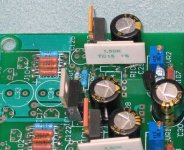
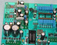
I am using the SCC944-05 input transformer. I lifted the primary ground connection on the transformer and only capacitively couple it to ground. On the secondary side, I use 2 center tapped 150 ohm resistors with the center tap tied to ground. Each 150 ohm resistor is bypassed with 22pf capacitors. I've used this technique in the past with good results.
I'm using a CS8414 and SOIC to DIP adapter instead of a CS8412 since I couldn't find any cS8412 chips. For the Filter components, I use SMD components right at the chip pins. I've also added extra SMD decoupling caps right at the power supply pins.
For the decoupling caps for the TDA1541, I'm using the epcos caps from Digikey. The 250v ones are a bit wide and need to have pins slightly bent to fit properly. It looks as if the lower voltage ones would have been better.
And for the I-V resistor, I'm using the Caddocks mentioned earlier. I'll include a few pictures.
---Gary
I've made some progress putting my boards together. In fact they should be ready to listen to as soon as one more transformer arrives from digikey. Here's what I've been doing / using for parts so far.
I am using the SCC944-05 input transformer. I lifted the primary ground connection on the transformer and only capacitively couple it to ground. On the secondary side, I use 2 center tapped 150 ohm resistors with the center tap tied to ground. Each 150 ohm resistor is bypassed with 22pf capacitors. I've used this technique in the past with good results.
I'm using a CS8414 and SOIC to DIP adapter instead of a CS8412 since I couldn't find any cS8412 chips. For the Filter components, I use SMD components right at the chip pins. I've also added extra SMD decoupling caps right at the power supply pins.
For the decoupling caps for the TDA1541, I'm using the epcos caps from Digikey. The 250v ones are a bit wide and need to have pins slightly bent to fit properly. It looks as if the lower voltage ones would have been better.
And for the I-V resistor, I'm using the Caddocks mentioned earlier. I'll include a few pictures.
---Gary
Attachments
Peter Daniel said:I'm using one of the early version of tube-lover kit I bought from another member who decided not to go with it.
I compared it with Pedja's schematic, and apart from PS, the output stage is the same. It sounds very good.
I wasn't really convined that parallel DACs can sound good, but if you connect oscillator caps on both DACs this brings it to a totally different level. The best DAC I tried so far. I'm also using S2 grade of TDA1541.
Yes, my parallel TDA1541 dac is based on Lesha's and Torben Kristens, connecting the oscillator caps does make a big difference, it seems some people had problems doing that but mine worked fine.
My TDA's are from Elib.
I was going to add CCS to the Anodes of the 6C45PI's but I'm going to build Pedja's dac first
t. said:
connecting the oscillator caps does make a big difference, it seems some people had problems doing that but mine worked fine.
I had some problems as well. If chips are not matched properly, it creates distortion. I swapped one of the chips with another one and it is fine now. So some matchig is definitely required, unless someone is lucky in a first place.
As to the 12 (or 14) bypass caps at the DAC, they make a difference too. I installed sockets so I can swap them and compare. Presently I have ERO MKT .33u and they sound decent enough. Will try BG NX .1 or .47 later.
Re: Board progress and Caddocks
While I'm using 110ohms only, I found that Caddack MK132 works pretty well here. The signature of resistors is pretty much detectable in this location as well.
I don't know what type of input transformer Thomas is using, but I actually found it sounding better than Scientific Conversion one.
GaryB said:On the secondary side, I use 2 center tapped 150 ohm resistors with the center tap tied to ground.
While I'm using 110ohms only, I found that Caddack MK132 works pretty well here. The signature of resistors is pretty much detectable in this location as well.
I don't know what type of input transformer Thomas is using, but I actually found it sounding better than Scientific Conversion one.
Peter Daniel said:
I had some problems as well. If chips are not matched properly, it creates distortion. I swapped one of the chips with another one and it is fine now. So some matchig is definitely required, unless someone is lucky in a first place.
I must have been lucky.
The main thing I noticed when I did that mod was the sound stage depth and precision increased a lot
Its good to see yours is coming along nicely gary!
Come on Chaps, where is all the others whith Pedja's dac PCB🙂
Come on Chaps, where is all the others whith Pedja's dac PCB🙂
Nice DACs, guys. 😉
Pedja
Interesting. Resistors directly to ground and no coupling caps?On the secondary side, I use 2 center tapped 150 ohm resistors with the center tap tied to ground. Each 150 ohm resistor is bypassed with 22pf capacitors. I've used this technique in the past with good results.
Pedja
Pedja said:Interesting. Resistors directly to ground and no coupling caps?
Pedja
Yes, you've got it right. Its a technique that was proposed quite a few years back by Pete Goudreau describing an extensive set of mods to the Parts Connection DAC. The idea is to provide a path to ground for common mode noise that manages to couple through the transformer.
I've tried this on several DACs and it works well.
---Gary
Its alive!
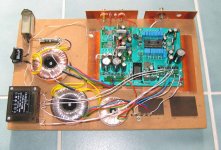
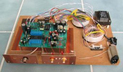
I'm happy to report that after a bit of soldering and lots of drilling and screwing onto my breadboard, I've got a working DAC. Amazingly enough for me, it worked first time out of the shoot.
Its still not very presentable but in this form its very handy for tweaking so I'll leave it this way while it burns in and I get a handle on the sound.
Thanks again to Pedja for sharing this project.
---Gary
GaryB said:I've made some progress putting my boards together. In fact they should be ready to listen to as soon as one more transformer arrives from digikey.
I'm happy to report that after a bit of soldering and lots of drilling and screwing onto my breadboard, I've got a working DAC. Amazingly enough for me, it worked first time out of the shoot.
Its still not very presentable but in this form its very handy for tweaking so I'll leave it this way while it burns in and I get a handle on the sound.
Thanks again to Pedja for sharing this project.
---Gary
Attachments
Nice work Gary!
Not sure about that mains filter though😉 I've tried them before and didn't like the results.
Anyway keep us up to date, all I need is the 14 x decoupling caps and a transformer and then mines finished.
BTW Pedja if your reading, would it be worthwhile trying 0.1uf or 0.47uf BG NX-HI Q for the 12 LSB decoupling caps? I just wondered
Worthwhile trying - no doubt, Leo. Bostjan Kragl (I hope he doesn’t mind that I’m forwarding this info) compared them at this place against WIMA FKP1 (which are superior to MKP10 in some performances that may be important here) and found them to be better. Two issues that may spoil the fun is their price and the fact this board can’t achieve what with them may be achieved in the term of the layout, namely the loops may be a few times shorter.
Pedja
Pedja
t. said:Nice work Gary!
Thanks.
Not sure about that mains filter though😉 I've tried them before and didn't like the results.
Well its easy enough to try without it. I'll solder in a standard IEC connector and see how it sounds. What's everyone else experience here? I thought the filter would be good for keeping digital noise from the DAC away from other componenets. Any thoughts on why the filter hurts the sound?
By the way, its already sounding very nice but I suspect that the Black Gates will need at least a week to really burn in. I also need to swap the TDA1541 out for a TD1541A S1 crown that I have. I wanted to make sure it worked before putting in the "good" chip. I originally rebuiilt an old Magnavox 472 back around 1990 and bought a crown chip at that time from Euphonic Audio based on some ads in Audio Amateur. The Magnavox had long ago been relegated to the junk pile so this was a good chance to salvage those old chips.
---Gary
Pedja said:Worthwhile trying - no doubt, Leo. Bostjan Kragl (I hope he doesn’t mind that I’m forwarding this info) compared them at this place against WIMA FKP1 (which are superior to MKP10 in some performances that may be important here) and found them to be better. Two issues that may spoil the fun is their price and the fact this board can’t achieve what with them may be achieved in the term of the layout, namely the loops may be a few times shorter.
Pedja
Cheers Pedja.
I'm tempted to go for the NX-HI Q's, I know the price is a bit high but I want to use the best parts I can for your dac🙂
Thing is do I go for 0.1uf or 0.47uf
GaryB said:
Thanks.
Well its easy enough to try without it. I'll solder in a standard IEC connector and see how it sounds. What's everyone else experience here? I thought the filter would be good for keeping digital noise from the DAC away from other componenets. Any thoughts on why the filter hurts the sound?
By the way, its already sounding very nice but I suspect that the Black Gates will need at least a week to really burn in. I also need to swap the TDA1541 out for a TD1541A S1 crown that I have. I wanted to make sure it worked before putting in the "good" chip. I originally rebuiilt an old Magnavox 472 back around 1990 and bought a crown chip at that time from Euphonic Audio based on some ads in Audio Amateur. The Magnavox had long ago been relegated to the junk pile so this was a good chance to salvage those old chips.
---Gary
Well I tried these filters in various cdp's,amps and a pre-amp.
They did help get rid of some of the mains noise but at the expense of flattening the soundstage and adding a sort of artificial sound.
Try it and see what you think.
I've got TDA1541A,S1 and S2, I know which I prefer😉
I also tried mains filter and didn't like it, it brought too much coloration (and veiling of getail) and none of the improvements.
- Status
- Not open for further replies.
- Home
- Group Buys
- TDA1541A non-o/s DAC PCB