When I installed my TDA1541 (noA) DAC chip, the unit (slowly?) died. 
The testsignals (minV):
PIN SHOULD L/R Measured L - Measured R
13, 18 7,5 V 9,30 7,65 (MSB)
12, 19 7,6 V 0 (zero) 7,78
11, 20 5,5 V 6,07 7,0
10, 21 5,25 V 5,77 5,64
9, 22 3,85 V 4,07 5,39
8, 23 3,8 V 4,11 4,04
7, 24 3,45 V 3,71 4,0
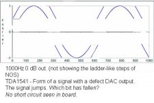
I tested the DAC out of the box with a 0 dB signal. And initially the output was OK (looking at the sine output) one channel, the other I had shorted two capacitor leads. The signal had ‘holes’ in them.
Corrected it, and for some time it was OK, but chip did get warm..
Then the signal got cut in two for the left channel: first half of the sine on the same level as the second (mean that the MSB is on both times).
I have tried for shortcircuits - none found. Strangely the second bit showed double the amount of nF (about 200) while all other capacitor leads showed the correct 100 nF. Internal short...??
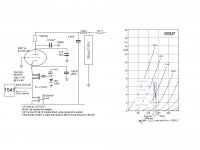
My schema:
I loaded the output with a FET – source follower configuration; a potentiometer gave the appropriate Vg of 1,7 volt in my case for the required Iout of 2mA. Initially loaded on the drain on a 1k5 (to 15V) resistor directly; later cascaded with a tube.
It gave a very nice step response.
Listening to it, the bass was a bit lacking but the highs were very liquid.
Questions:
Is the 0 dB sine wave too much?
Or is such an output loading with a FET far tooo dangerous? With a high current at startup? Methinks that a 15-30 ohms resistor should then be equally suspicious!
Am I just aping around?
Jocko mentions that he saw hundreds of TDA1541’s faint under his eyes in a stresstest and even some died on the table as well.
The chip is too expensive to just buy another one… without understanding my problem.
The testsignals (minV):
PIN SHOULD L/R Measured L - Measured R
13, 18 7,5 V 9,30 7,65 (MSB)
12, 19 7,6 V 0 (zero) 7,78
11, 20 5,5 V 6,07 7,0
10, 21 5,25 V 5,77 5,64
9, 22 3,85 V 4,07 5,39
8, 23 3,8 V 4,11 4,04
7, 24 3,45 V 3,71 4,0
I tested the DAC out of the box with a 0 dB signal. And initially the output was OK (looking at the sine output) one channel, the other I had shorted two capacitor leads. The signal had ‘holes’ in them.
Corrected it, and for some time it was OK, but chip did get warm..
Then the signal got cut in two for the left channel: first half of the sine on the same level as the second (mean that the MSB is on both times).
I have tried for shortcircuits - none found. Strangely the second bit showed double the amount of nF (about 200) while all other capacitor leads showed the correct 100 nF. Internal short...??
My schema:
I loaded the output with a FET – source follower configuration; a potentiometer gave the appropriate Vg of 1,7 volt in my case for the required Iout of 2mA. Initially loaded on the drain on a 1k5 (to 15V) resistor directly; later cascaded with a tube.
It gave a very nice step response.
Listening to it, the bass was a bit lacking but the highs were very liquid.
Questions:
Is the 0 dB sine wave too much?
Or is such an output loading with a FET far tooo dangerous? With a high current at startup? Methinks that a 15-30 ohms resistor should then be equally suspicious!
Am I just aping around?
Jocko mentions that he saw hundreds of TDA1541’s faint under his eyes in a stresstest and even some died on the table as well.
The chip is too expensive to just buy another one… without understanding my problem.
Attachments
Hi, I think the shorts at the output caused your problem. Chips in general hate shorts. This one is bipolar and antique so it should be handled with some care 😉 BTW was it a new one or a desoldered one ?
Your measurements show enough evidence that the chip fails. True, early TDA1541 sometimes die after a period of producing a crackling noise in one channel first. This really counts especially for the first versions ( I know it with pre 1989 non A versions ) as far as I experienced the problem. I haven't experienced this with the more recent versions yet. Please realise that the new ones of course haven't had as many hours on them as the old ones. At least 15 years of reliable service seems enough, isn't it ?
Maybe you can spend another 10 Euro for a new TDA1541A and try a standard output stage to start with ???
jean-paul said:Hi, I think the shorts at the output caused your problem.
BTW was it a new one or a desoldered one ?
Your measurements show enough evidence that the chip fails.
Maybe you can spend another 10 Euro for a new TDA1541A and try a standard output stage to start with ???
I actually shorted the capacitor leads (I think it was pins 23/24).
It was new.
Jean Paul, Is the output stage suspect?
I added the current waveform, fun to look at just as evidence. The LSB also tends to wobble a bit.
Attachments
triode_al said:The chip is too expensive to just buy another one… without understanding my problem.
 You live in holland, don't you? Go to any flea-market or marktplaats and get an old philips/aristona/erres/maganavox/marantz. Good chance you get one there.
Last one i picked up (from a bar 4 free) was an old cdm2 based player. Still works, just the transistors for the traymotor are burned. Looks like it had major abuse over the years, dust and dirt (smoke) everywhere. But those things keep on going.
Extreme_Boky said:Have you checked the transients when turning your analog (valve!) stage ON and OFF?
Extreme_Boky
What I see (tube used in cascode) is that the output goes down - to min 15 V of course. The 2SK30 pulls it down to earth.
If I would have a transistor cascode this would not be the case.
I reckoned that this is a normal state as the current drain is also to the -15V rail.
I tested one setting with an opamp controlling the Vout and keeping this to zero, this would not have orked anymore in this setting with a tube.
In the mean time I have found a schema, by the way, from Marantz, with a separate opamp only for the 2 mA. That will circumvent any DC going astray. This is in the DFA888 (that I bought 2ndhand last month) (see shema Philips/Maranntz)
--> Maybe an idea to combine the two topologies?
Still the 3,5 mA CCS from the 2SK30 is needed to bias the tube to a lineair area. So when working, that is OK.
When turning off, there is no transient effect I saw.
Attachments

How is that 4uF decoupling cap connected to ground / what ground - power supply ground?
Make sure there is no charge / discharge current from this capacitor running through signal ground.
Marantz cct shows that keeping 0 at DAC Iout is important. So, try to keep it at 0. Once you are happy with this, try another TDA chip. I can get them for around $A20 each.
Good luck,
Regards,
Extreme_Boky
Extreme_Boky said:How is that 4uF decoupling cap connected to ground / what ground - power supply ground?
Make sure there is no charge / discharge current from this capacitor running through signal ground.
Good point, I actually don't have it connected to -15V but intended to. This just because that is where the signal terminates that starts high up (or the other way around, for the physicists). This would give the shortest path.
But I see the difficulty here.
The shunt regulator should stop any transient though. Apart from the warm up, that is... :-(
jean-paul said:. True, early TDA1541 sometimes die after a period of producing a crackling noise in one channel first.
YES...
I got a new early TDA1541AS1(Yes,S1!) last year, but it produce a crackling noise in one channel
Should heatsinks be used on these?
I've just bought 5 3"x3"x1" heatsinks to put on the 5 TNT 1541 I'm going to build.
I've just bought 5 3"x3"x1" heatsinks to put on the 5 TNT 1541 I'm going to build.
The "analogue" half of 1541 where -15v analogue supply is, runs hotter than the other half of the chip. This heat in hot environment (30-40 C), closed enclosure and over long period of time could do some harm. I used copper sheet on top of the chip and bent sides which I soldered (both!) to the ground plane. I think I saw somewhere someone "sandwiched" 1541A between 2 copper sheets...
Extreme_Boky
Extreme_Boky
I thought I saw RF shields in some equipment, and even read text stating that copper is much better for RF shielding than plumbing - but -- disguise -- it is a heatsink!
jean-paul said:you mean lead when you write plumbing ??
Probably, yes, but it does sound silly, doesn't it!
Anyway, sandwitches of copperfoil/ironplate/foil would be better for RF; and iron is a bad conductor of heat.
For heat conduction: aluminum should equally work out fine.
Recapitulating, if the -15V current -source gets hot, then it is not the 0dB track that heats it up, isn't it. Still, I wonder if there are special sound-track situations that have an adverse effect and heat up the chip more than standard operation.
- Status
- Not open for further replies.
- Home
- Source & Line
- Digital Source
- TDA1541 end of life