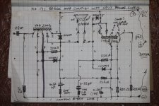
HERE IS THE15 TH ATTEMPT --FIG 17 -bridge amp conf with split power supp-drawing of
here is the 15 th attempt at constructing a home wired TDA 2006
BRIDGE AMP CONFIGURATION WITH SPLIT SUPPLY--
(TWIN TDA CHIPS )
note the 2nd TDA is reversed --makes wiring pinout a bit awkward
maybe wires too long causing oscillation --
but this fella roars like a black maned LION with pyles--
have made so many amps ---- eg--the
TDA 7294 I BUILT 5 YRS AGO ----140 WATT mono amp
worked wonderful --till I blew it on overdrive solos with a
Gibson les Paul humbucker ---- but zero distortion --until now!
so all I want is a modest 21 or 24 watt(above ) that behaves itself
many thanks for all your help --
you are a true Samaritan ---- ( I think I have attached without using IRFANVIEW --- my camera has a small reduced pixel setting --
regards -- carl
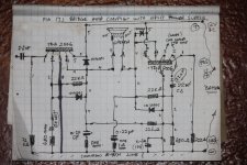
(bridge amp twin conf--corrected drawing
sorry missed drawing in the 680 ohm resistor bottom of pin 2 and its series
22 uf capacitor ---also left out the 22 uf cap--c6 in the drawing -- on the other TDA Pin 2 ---
(they are included in the circuit I constructed --just forgot to DRAW them in ------apologies ---
so I fotographed the drawing (corrected) again---
here is the original DISTORTING circuit
redrawn with all components ---
see if u can spot the GREMLIN !
will really appreciate if u can redraw another circuit for me --
this one is a nightmare --due to opposing TDA AMPS--
OBVIOUSLY something is very wrong ---please feel free to tear it to pieces ----
regards -- Carl---APOLOGIES for not drawing in those vital components
Attachments

Hi Mark ---
apologies for the battle to send u a decent drawing
sorry for the ommisions --finally I got a picture uploaded--
thanks so much for your advice ---but now I am really confused--
TWO 12 VOLT BATTERIES ?---IN SERIES ?
I cannot understand how the circuit can be 24 volt when the schematic shows
12 VOL split supply ---no real twin battery connection shown --
how on earth do I connect 2 x 12 volt batteries?
can u send me a drawing or correct my twin bridge AMP -
I don't see how to connect 2 batteries --this has me perplexed?
esp whaen you say -12 Connects to pin 3 ? where do I connect o ( zero?) to ground ?----what is zero ---? ground ?? ----do u mean earth or negative poles of both batteries --?
the reason why I draw constructed the first SINGLE SUPPLY TDA 2006 circuit schematic ----is that it says SINGLE 12 VOLT BATTERY ----- ? is that wrong ?
the second ( fig 17 ) shows ( SPLIT SUPPLY bridge amp config )
what does split supply mean --? 2 x 6volt batteries ? nowhere does it indicate on any schematics that you must use 24 volts supply !
I am now so confused --how do I wire up 2 x 12 volt series batteries ---into the bridge amp config diagram -
CAN YOU SEND ME A DRAWING OF HOW TO CONNECT ---I AM TERRIFIED I MAY BURN OUT THESE SENSITIVE TDA 2006 IC ,S
many thanks --but your advice is too brief ---need far more elaboration
ie --- pin 3 to zero ?? where do I find zero point ?
please help
really appreciate ---
CARL
THE
Here is the page for the irfanview plugins,
IrfanView PlugIns
Just save them to your drive and double click on it and they will self install as long as you have irfanview installed as well.
jer 🙂
IrfanView PlugIns
Just save them to your drive and double click on it and they will self install as long as you have irfanview installed as well.
jer 🙂
Last edited:
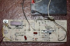
FOTO OF MY CIRCUIT - fig 17 bridge amp ( twin TDA 2006 AMP)
Hi mark --
here is a foto of the actual bridge amp conf fig 17 --converted
to a practical format for wiring up both opposing TDA,s
can u show me where precisely to connect 24 volts to what PINS
THE MANUFACTURER EMPHASISES 12 --16 VOLTS SUPPLY
cannot find 24 volt wiring diagram anywhere --I really need a 24 volt
actual SCHEMATIC --NO WONDER THE DAMN THING NEVER WORKED
--NO MENTION ANYWHERE OF 2X 12VOLT BATTERIES IN SERIES
but you are right ---weird connections --not for amateurs --!
I cannot still figure what 0 means ? --NEGATIVE VOLT ? NEGATIVE TERMINAL? ?? ZERO VOLTS ??
WHY DOES THE FIRST ( TYPICAL SINGLE SUPPLY DISTORT )
Does the single TDA 2006 CIRCUIT ( IE THE very first typical circuit shown in the makers PDF ) does that use two x 12 volt batteries as well /?
OR if I build the first single supply circuit----- AGAIN ( for the 12 th time!----can u show me how to connect TWO 12VOLT BATTERIES IN SERIES INTO THE SINGLE SUPPLY SCHEMATIC ??--- or is that incorrect??😕
CAN U SEND ME A DRAWING ---THE SINGLE TDA CHIP IS ALL I WANT -( 12 WATT ) --I only built this dual chip monster to STOP DISTORTION !
OK now I am in a realy dilemma ---those schematics were so misleading =
maybe intentionally -- so u have to burn out your circuit --then the chip maker scores big time on fools like me who keep buying chip after chip
--sods !--but its my fault --rushing in without heeding any warning signals
conveniently provided --cost me a small fortune --replacing batteries
ordering brand new components etc --
ok enuf grumbling --here is my 15 th attempt that drove me up the wall !
Attachments
got IRFANVIEW
Hi GERALD --
THANKS --got IRFANVIEW downloaded ---
but no idea what a plug in is ---
no problem --my camera has the small quality /downsize
setting you recommended--ie 1024 x 768 ---
I did get the fotos and drawings to attach --many thanks to your
superb advice ---thanku so much --
I have successfully posted all thosr=e circuits --
sent some to Mark Whitney ---- who instantly gave me
an answer --- TWO x 12 volt batteries in series ---
I was blown away --
but I cannot understand how to connect 2 batt into this twin amp fig 17 bridge circuit -----he mentions
=12v to pins 5
0 ??---to ground ? --( no idea what zero means )
NEG 12V to pins 3 ----? --- lost me totally --
I really need a clear diagram or drawing to connect these 2 series 24 volt
power into my-- SIMPLE SINGLE CIRCUIT--THE FIRST SCHEMATIC --PAGE 1
circuit ----WHY no MENTION OF 24 VOLTS IN THE PDF makers schematic
circuits for TDA 2006 -?-- WHY DID THEY FAIL TO MENTION THIS ?
as you can read --only 12 VOLT SPLIT SUPPLY ( VERY CONFLICTING /MISLEADING INFO )
no wonder the chip amp DISTORTS
REALLY NEED JUST THE SINGLE SUPPLY 12V FIRST SCHEMATIC -
10 -12 WATT ----THATS ALL ---NOW HOW DO I CONNECT 2 X 12 VOLT BATTERIES INTO THIS SINGLE CHIP CIRCUIT ? WILL IT DISTORT AGAIN ?
PLEASE HELP ----24 VOLTS ----? BAFFLED!-- PLEASE read the replies
and see all fotos --
CARL😕
Attachments

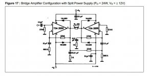
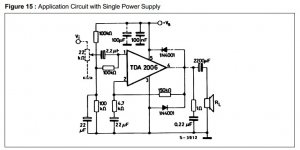
"Split supply" as required for the TDA2006.
For a single supply implementation you need to add extra parts and twice the voltage. See figure 15 and 16 of the datasheet.
first CIRCUIT --ON PDF
HI Mark ---very grateful again -
thanku for the diagrams of series 12v connections
ALL I WANT IS THE VERY FIRST CIRCUIT --THEY call a " typical
TDA 2006 CIRCUIT ___"---
THE first simple one ---
now --does that require a 12 volt single battery ?
or two 12v -(24 volt batt series connection )?
because I really wanted only a 12 watt light weight portable amp
2 x 12volt batteries -- are too bulky /complicated --
no idea how to connect 24 volts into that twin bridge fig 17 amp
conf ---don't need it --only tried it cos I thought it may NOT DISTORT
like all the others
ok - CAN U SEND ME A SIMPLE DRAWING OF HOW TO CONNECT 12 V
INTO THE FIRST --VERY FIRST CIRCUIT --
THATS THE ONE I WANT TO BUILD AGAIN PROPERLY WITHOUT
DISTORTION ---FOR THE 16 TH TIME
PLEASE HELP ---I AM LOST AS TO HOW YOU CONNECT 12V INTO A SINGLE TDA AMP ---( NOT THE 100K OHM DOUBLE COMPONENT CIRCUIT
--ONLY THE VERY FIRST ONE ---
DOES THAT ALSO REQUIRE 24 VOLTS --IN SERIES ?
I AM NOW SO BAFFLED --AS THE MAX RATED VOLTAGE IN THAT PDF
ON TDA SEZ MAX VOLTS 15 ----!
OK THANKS------CARL
You can connect my PSU schematic to any of the schematics with split power supply, +Vs to +Vs, -Vs to -Vs and GND to GND.
According to the datasheet the minimum Supply Voltage is ±6V, meaning plus and minus 6V or a single supply of 12V. With a 12v single supply the maximum output power is only going to be about 5 watts into a 4 ohm load.
For a single power supply use diagrams 15 and 16. See the 2200uF capacitor at the output and the extra resistors at the input.
Last edited:
thanks MARK ---
err --what is a PSU schematic?---I still do not know what is meant by a
SPLIT POWER SUPPLY--
ok --have built that fig 15 single power supply 5 times --
it has 3 100 k ohm resistors cluttered around pin 1---
input------ I used 2200 uf ---1000 uf caps at output --
alas --terrible distortion --
I CANNOT VISUALISE THE 12 VOLT BATTERY CONNECTIONS TO ANY OF THE
CIRCUITS -----I REALLY NEED A DIAGRAM ---SCHEMATIC ---A HAND DRAWN CIRCUIT WILL SHOW ME INSTANLY EXACTLY WHERE TO CONNECT EACH 12 VOLT BATTERY POS AND NEG TERMINALS---I DO NOT UNDERSTAND YOUR SERIES DIAGRAM ---SHOWING A MIDDLE POINT BETWEEN THE 2 SERIES 12V BATTERIES--
THAT MEANS THAT MIDDLE POINT CONNECTS WHERE EXACTLY?
OK --U SAY --12V POS TERMINALTO PINS 5 AND 5 ON EACH SIDE OF THE STEREO TWIN TDA CHIPS---AND WHAT GOES TO PINS 3 AND 3 ---ON EACH SIDE OF EACH
SEPARATE TDA CHIP?----THE NEGATIVE /EARTH TERMINAL ---? THAT IS 24 VOLTS RIGHT ??--- OK THEN WHERE DOES THAT INBETWEEN 2 BATTERIES TERMINAL
GO TO ??? That's where I lose this whole plot ---
anyhow all I really want is the VERY FIRST CIRCUIT 21 V THE SIMPLE ONE SINGLE
IC GIVES 12 WATT ----BUT MY PROBLEM IS --WHY DOES IT KEEP GROWLING WHILST ITS OBVIOUSLY AMPLIFYING ( THE CHIP HEAT SINK GETS WARM --OK
THE RADIO OR GUITAR INPUT SIGNAL IS LOUD ---BUT THAT FUZZ
crackle !!
please give me a sketch of the wiring power supply to fig I circuit ---please ?
The datasheet for this chip has everything you need in it TDA2006 Datasheet pdf - 12W AUDIO AMPLIFIER - ST Microelectronics
Attachments
RETURN OF THE MONSTER
OH my god --no no thank you
hello Jerloowoo ---
sorry mate that TDA PDF is the cause of all the problems!
I think you have not been following this nightmare circuits
that distort so badly ---its a horror
I DOWNLOADED THAT TDA PDF U JUST SENT ME --3 MONTHS AGO
-----THAT IS THE PROBLEM --
PLEASE READ ALL MY QUESTIONS /REPLIES
THOSE CIRCUITS APPARENTLY --ARE 24 VOLT ( SERIES )
VERY WRONG AND MISLEADING SCHEMATICS ONLY SAY 12 VOLTS !!
THE DAMN THINGS ONLY WORK ON 24 VOLTS -
JUST ASK MARK WHITNEY -- (SEE THREADS ---ETC )
I HAVE NO IDEA HOE TO CONNECT UP 24 X2 BATTERIES
INTO THESE 12V CIRCUIT S ---WHat hell I have endured
buil t 15 of those nasty circuits --- ALL DISTORT
BECAUSE I GOT THE VOLTAGE WRONG --THANKS TO THAT IDIOTIC
TDA INFO NONSENSE --READ FOR YOURSELF --ITS A NIGHTMARE !
THANKS ANYWAY ---I WANT TO BE AS FAR AWAY FROM THIS
STUPID TDA CHIP AMP ---ITS MADE ME SO SICK --TRIED EVERYTHING
FAILED ------IF U DARE --TRY TO BUILD IT ---- VERY MISLEADING INFO
SEE YA CARL
this IS THE CIRCUIT I NEED TO BUILD( AGAIN)
YO MARK -
I HAVE DRAWN CAREFULLY THAT FIRST TDA CIRCUIT FOR YOU TO
ADD THE VERY ESSENTIAL VOLTAGE CONNECTION METHOD --THAT HAS CREATED THE DISTORTION IN YHR FIRST PLACE
THIS IS MY PRACTICAL CIRCUIT ---WIRED LOGICALLY FOR SIMPLICITY -
PLEASE SHOW N -ME HOW 12VOLT OT 24 VOLT CONNECTS WHERE
ABOUTS ---??----CARL-
---PLEASE ----B4 I LOSE MY MIND !---JUST SEND BACK TO ME WITH ALL THE BATTERY CONNECTIONS THAT I CANNOT FATHOM ----REALLY
WILL SORT THIS PROBLEM ONCE AND FOR ALL --😕
Attachments

Looks to me like you are missing the output capacitor. 2200 micro F.
With single 12V power supply, you have 6 volts on the output leg of the TDA.
Capacitor is needed to stop DC voltage going to the speaker.
With single 12V power supply, you have 6 volts on the output leg of the TDA.
Capacitor is needed to stop DC voltage going to the speaker.
PSU schematic is at post 29.
The middle point connects to the amp GND (ground), -Vs doesn't connect to GND. Add the schematic from post 29 to schematic 15 of the datasheet.
The heatsinks are far to small and you need to reduce the lengths of the component leads.
Plenty of LM1875 / TDA2030 point 2 point / p2p examples on internet, but first its more important to understand what you are building and how it works. I will look for some good websites for info.
Hi.
Just looked again at the IC datasheet and your drawing.
You are trying to use a symmetrical power supply application , with single 12 volt's. It won't work. Follow the schematic with 2200 micro farad capacitor on the output and it will be ok with 12 volt battery
Just looked again at the IC datasheet and your drawing.
You are trying to use a symmetrical power supply application , with single 12 volt's. It won't work. Follow the schematic with 2200 micro farad capacitor on the output and it will be ok with 12 volt battery
Also the connection between leg 2 and 3 in your schematic is wrong. R1 22k resistor should only be connected to leg 2.
Last edited:
CHECK AGAIN --PIN 2 AND 3 ARE CONNECTED HUMBERTO --
THERE IS NO 2200 MF CAP ON THE FIRST SCHEMATIC CIRCUIT
PLEASE D/L THE TAD PDF ----LOOK CAREFULLY --
HAVE BEEN 3 MONTHS -15 CIRCUITS LATER --ALL 3 SCHEMATICS DISTORT
SO --DISCONNECT LEG 2 AND 3 --? CIRCUIT DIES MY FRIEND !
BEEN OVER IT A THOUSAND TIMES
IF ANYONE CAN SEND ME A SUCCESSFUL WORKING TDA 2006 CIRCUIT
WITHOUT DISTORTION --INSTEAD OF UNPROVEN THEORIES --I WILL BE VERY GRATEFUL - BUT NO-ONE HAS SENT ME A WORKING CIRCUIT IN 4 DAYS
EASY TO CRITISISE ---4 HEAVENS SAKE ---GO BUILD THE 3 CIRCUITS
AND PROVE U ARE A BETTER PERSON --I WILL APOLOGISE UNCONDITIONALY
THANKYOU ALL ---BUT WE ARE GETTING NOWHERE REGARDS --CARL
EXCEPT MARK WHITNEY ---WHO TELLS ME THE CIRCUITS ARE 24 VOLT SERIES
2 X 21 VOLT BATTERIES -NOT 12 VOLT !
BUT I CANNOT SEE HOW TO CONNECT 24 VOLT TO ANY OF MY DOZEN ATTEMPTS
I NEED A CLEAR CIRCUIT DRAWING PLEASE PLEASE
Last edited:
- Status
- Not open for further replies.
- Home
- Amplifiers
- Chip Amps
- TDA 2006 amplifier