Dear Friends!
I would like to share with a few amplifiers ideas (some of the are playing already!).
The ideas were born after reading 2004 blogs by John Broskie in TCJ.
Very similar ideas could be found on the sites of Evolve Power Amplifiers.
The pdf file consists of 3 projects with the results of simulations.
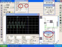
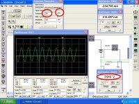
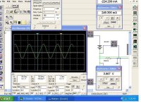
First two have 75mV 1 kHz sine wave at the input. The transistors are 2n2955/3055. Those are only ideas.
Third has at the input 1V 1kHz sine wave. The transistors are IRF540/9540. This amp I have built in two versions:
• First – power supply voltage only +-13V, signal directly from a source, potentiometer, connected to the 10kOhm resistors (in the middle). NFB resistors 12kOhm. In power supply ordinary parts. Sound: GREAT from the start. Detailed and not grainy. quick, deep, low bass, wide stage, wooden saxophones, vocals not sharp. It works stable from 11-2004. Rest current only 200 mA per hexfet.
• Second: - As a preamplifier connected via a paper in oil capacitor, I have used E88CC supplied from only +43VDC power supply (!). 180 Ohm at the cathode, 4.7 kOhm at the anode. The capacitor at the solid state side was terminated to a ground via the 380 kOhm resistor. Power supply +-23V, super fast diodes, battery of paralleled good, fast capacitors. Rest current 350 mA per hexfet.
Now some notes about the sound: VERY good bass, detailed mids and highs, deep stage, but a little too bright sound. Saxophones are a little metallic, not like in tube amps when you could hear the wood.
In a comparison with a tubes it sounds metallic and bright. I am used to tubes and for the first hearing I was disappointed, and thought that it sounded like kick in the balls (Carlos will be happy reading this). But after some time amplifier started to sounded more smooth and culture. Now I like it especially that is better of any solid state amplifier that I have ever heard.
I am curious of your impressions after building of those simply circuits!!!
I would like to share with a few amplifiers ideas (some of the are playing already!).
The ideas were born after reading 2004 blogs by John Broskie in TCJ.
Very similar ideas could be found on the sites of Evolve Power Amplifiers.
The pdf file consists of 3 projects with the results of simulations.
First two have 75mV 1 kHz sine wave at the input. The transistors are 2n2955/3055. Those are only ideas.
Third has at the input 1V 1kHz sine wave. The transistors are IRF540/9540. This amp I have built in two versions:
• First – power supply voltage only +-13V, signal directly from a source, potentiometer, connected to the 10kOhm resistors (in the middle). NFB resistors 12kOhm. In power supply ordinary parts. Sound: GREAT from the start. Detailed and not grainy. quick, deep, low bass, wide stage, wooden saxophones, vocals not sharp. It works stable from 11-2004. Rest current only 200 mA per hexfet.
• Second: - As a preamplifier connected via a paper in oil capacitor, I have used E88CC supplied from only +43VDC power supply (!). 180 Ohm at the cathode, 4.7 kOhm at the anode. The capacitor at the solid state side was terminated to a ground via the 380 kOhm resistor. Power supply +-23V, super fast diodes, battery of paralleled good, fast capacitors. Rest current 350 mA per hexfet.
Now some notes about the sound: VERY good bass, detailed mids and highs, deep stage, but a little too bright sound. Saxophones are a little metallic, not like in tube amps when you could hear the wood.
In a comparison with a tubes it sounds metallic and bright. I am used to tubes and for the first hearing I was disappointed, and thought that it sounded like kick in the balls (Carlos will be happy reading this). But after some time amplifier started to sounded more smooth and culture. Now I like it especially that is better of any solid state amplifier that I have ever heard.
I am curious of your impressions after building of those simply circuits!!!
Attachments
I too have seen the circuit that you mention on the Evolve site. I even considered building a version. Nice to know that you did it successfully!
I would love to see the schematic of the Second version with FETS including the tube stage.
-Doug
I would love to see the schematic of the Second version with FETS including the tube stage.
-Doug
Yessss!...yeahhh!...good!.... very good to see you here Pada
And of course i like the things you do...of course.
And i will hear them...also of course.
Carlos
And of course i like the things you do...of course.
And i will hear them...also of course.
Carlos
Re: Yessss.... i like all those circuits, including Susan Parker designs
Hi Carlos,
low power transistors = low offset,
in practice I had to regulate the offset paralleling one of the nfb resistors with another resistor (rather high value ~1MOhm).
destroyer X said:But transformer are heavy when fall down into our fingers.....hummm this is not too much stimulating to me.
regards,
Carlos
Hi Carlos,
low power transistors = low offset,
in practice I had to regulate the offset paralleling one of the nfb resistors with another resistor (rather high value ~1MOhm).
Dozuki said:I too have seen the circuit that you mention on the Evolve site. I even considered building a version. Nice to know that you did it successfully!
I would love to see the schematic of the Second version with FETS including the tube stage.
-Doug
Hi Doung,
the tube section is not a realy sophisticated circuit:
common cathode circuit
with a res 180 Ohm as cathode res,
and 4.7 kOhm res at anode.
The signal is leaded by paper in oil capacitor to the current amp.
the input signal is connected to a e88cc's grid via a 470 kOhm Alps potentiometer.
Luke, use the force, and imagine this😉
Now I do not have chance to send this circuit at the Forum, I will do it later.
CzeϾ
When you re-write schematics but change ground with output symbols (so that supply is no longer floating and output is emitter follower) all starts to look quite ordinary. Only the input signal is kind of 'bootstraped'.
what feedback circuit do you use?
When you re-write schematics but change ground with output symbols (so that supply is no longer floating and output is emitter follower) all starts to look quite ordinary. Only the input signal is kind of 'bootstraped'.
what feedback circuit do you use?
darkfenriz said:CzeϾ
When you re-write schematics but change ground with output symbols (so that supply is no longer floating and output is emitter follower) all starts to look quite ordinary. Only the input signal is kind of 'bootstraped'.
what feedback circuit do you use?
No hej!
ale upa³!
the feedback resistor is connected between the drain and the gate of the hexfets or collector/base in case of bjts.
The feedback resistors are R1 and R2 in the 2nd schematic: when there is a positive input signal, Q2's base goes up, and the current going through the Q2C goes up. Current is being sucked from the ground through R3 (load), which gets fed to R1 through V2 to reduce the voltage on Q2B -> negative feedback.
I haven't analyzed this in great detail but you need to isolated power supplies (not a big deal), and they need to be super quiet as well.
It is, however, very fast, as the signal being feedback is current, and the output signal is current, regardless of what R3 is. In essence, this is a voltage->current amplifier. Very cleaver design.
On a 2nd thought, there is really no reason to have different feedback factors for the upper and lower devices and the power supplies are just pass-through for the feedback. So one way to feedback may be to eliminate R1 and R2 and replace it with one resistor going from N1 to the input resistor.
As a current amplifier, this amp has the unique chacteristics of a) lower output on lower / tougher load; b) lower feedback on lower / tougher load.
As a current amplifier, this amp has the unique chacteristics of a) lower output on lower / tougher load; b) lower feedback on lower / tougher load.
tlf9999 said:On a 2nd thought, there is really no reason to have different feedback factors for the upper and lower devices
I have regulated the offset in that way
tlf9999 said:So one way to feedback may be to eliminate R1 and R2 and replace it with one resistor going from N1 to the input resistor.
how about current setting? how about the offset?
tlf9999 said:
As a current amplifier, this amp has the unique chacteristics of a) lower output on lower / tougher load; b) lower feedback on lower / tougher load.
... and some more general rules with constant value of the gate resistors:
a) as lower the power supply voltage - as more feedback is needed (lower valued resistor) to yield right current through the hexfets,
b) opposite: as higher power supp. voltage - as less feedback is needed and the sound might became more interesting (because I think that nfb signal taken from a speaker, even through power supply, might spoil the sound - 'cause the speaker generates the electric waves which nfb tries to "mend").
padamiecki said:how about current setting? how about the offset?
what about running a CCS through those resistors instead? You can tie the CCS with the output devices to prevent thermal runaway - like you would in a normal bias setting.
padamiecki said:because I think that nfb signal taken from a speaker, even through power supply, might spoil the sound - 'cause the speaker generates the electric waves which nfb tries to "mend".
you don't need to worry about "back EMF" as this is a transconductance amplifier: the output current is in direct proportion to the input signal. Whatever you get from the non-existent back-EMF is irrelevant.
tlf9999 said:
you don't need to worry about "back EMF" as this is a transconductance amplifier: the output current is in direct proportion to the input signal. Whatever you get from the non-existent back-EMF is irrelevant.
this is strange for me, but my electronic knowledge is rather weak,
does it mean that the feedback resistors do not introduce a local/global feedback?

so you might have right,
especialy that I liked its sound
anyway I am surprised

I can see, that these simply project has focused an attention of some of you.
As I have mentioned before, the first was the best.
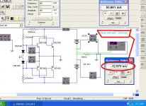
Attached you will find whole circuit which works from 2004 now on.
It is very easy to build even for every greenhorn.
The results that I have got with the ordinary quality parts have astonished me.
I believe that this is a good start to make the improvements.
tlf9999 proposed to use CCSes, but I can feel that this might spoilt the simplicity of this project, however, it is very hard to build simply and good amplifier. Everybody here knows this fundamental true. So why not to try?
Please be sure that this circuit is very flexible to the modifications, and bellow I proposed a few of them:
• Use of stabilised power supply, even with a global nfb, to minimise its impedantion, what ensures reliable conditions of working hexfets (but the whole impedantion will be more than on attached circuit, which consists only of secondary inductivity, the bridge and the capacitors), and with the possibility of regulation of the supply voltage = easy corrected offset.
• Use of many good quality paralleled parts (resistors, capacitors, and transistors), fast diodes, big low impedantion transformers, etc.
• Use of complementary hexfets pairs IRF 530/9540 which ensure better symmetry (but lower output power, what showed the simulations) instead 540/9540. However personally I would not try this solution.
• Use of IRF230/9240 (? look at above notes).
• Use of very good quality preamplifier to improve overall gain, and implement of global NFB (who knows, might be this will sound good?) to minimise distortions.
The hexfets from attached project are mounted on very small heatsinks. During the work they are hot, but I can touch them without the 1st degree burns ;-))) at about 50°C.
The transformer has got at about 18W power, without the load he yields 2X15~V, under working conditions 2X13~V. During the work heats up to 40°C.
Yes,
neat,
but works!
As I have mentioned before, the first was the best.
Attached you will find whole circuit which works from 2004 now on.
It is very easy to build even for every greenhorn.
The results that I have got with the ordinary quality parts have astonished me.
I believe that this is a good start to make the improvements.
tlf9999 proposed to use CCSes, but I can feel that this might spoilt the simplicity of this project, however, it is very hard to build simply and good amplifier. Everybody here knows this fundamental true. So why not to try?
Please be sure that this circuit is very flexible to the modifications, and bellow I proposed a few of them:
• Use of stabilised power supply, even with a global nfb, to minimise its impedantion, what ensures reliable conditions of working hexfets (but the whole impedantion will be more than on attached circuit, which consists only of secondary inductivity, the bridge and the capacitors), and with the possibility of regulation of the supply voltage = easy corrected offset.
• Use of many good quality paralleled parts (resistors, capacitors, and transistors), fast diodes, big low impedantion transformers, etc.
• Use of complementary hexfets pairs IRF 530/9540 which ensure better symmetry (but lower output power, what showed the simulations) instead 540/9540. However personally I would not try this solution.
• Use of IRF230/9240 (? look at above notes).
• Use of very good quality preamplifier to improve overall gain, and implement of global NFB (who knows, might be this will sound good?) to minimise distortions.
The hexfets from attached project are mounted on very small heatsinks. During the work they are hot, but I can touch them without the 1st degree burns ;-))) at about 50°C.
The transformer has got at about 18W power, without the load he yields 2X15~V, under working conditions 2X13~V. During the work heats up to 40°C.
Yes,
neat,
but works!
Attachments
Balanced input
Hi padamiecki
I like your simple design and I would like to built this amp with balanced input without capacitors(my preamp has balanced output) Have you some Hint for me ?
Hi padamiecki
I like your simple design and I would like to built this amp with balanced input without capacitors(my preamp has balanced output) Have you some Hint for me ?
Re: Balanced input
hm, rather impossible
you have to use those capacitors, they are essential
volavola said:... and I would like to built this amp with balanced input
hm, rather impossible
volavola said:without capacitors(my preamp has balanced output) Have you some Hint for me ?
you have to use those capacitors, they are essential
- Status
- Not open for further replies.
- Home
- Amplifiers
- Solid State
- TCJ - Evolve simply and good amps idea