Hi all,
Here is an updated version of the Autobias TBP-zero-SE (see Post 15).

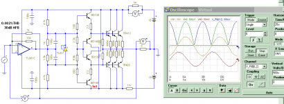
Don't freak out over the clutter - it is because there needs to be 14 electrothermal widgets to see if current hogging is happening or not. Hogging can be evaluated by offsetting one of the transistors in parallel with 5mV (V11 top right) giving about 50mA more idle current than the others. The start and end peak currents are monitored for parallel transistors to see if the difference stabilize after warmup (below).


Cold difference at the peak is 32mA and hot is 35mA. There is a slight increase. But what is more important is the final reading is stable once the temperature is stable. Here it seems to be stable so there's appears to be no hogging.
One helpful modification in this version is the MOS diodes and the autobias spreader transistors are biased with a bootstrapped +-12V 1W converter. This gives good PSRR and is not affected by rail voltage changes (assuming the converter is regulated). Also the autobias spreader does not need constant current sources for biasing which means 4 less transistors.
The attached file includes the latest electrothermal version above and the same as a non-thermal autobias version (run this for THD).
Here is an updated version of the Autobias TBP-zero-SE (see Post 15).
Don't freak out over the clutter - it is because there needs to be 14 electrothermal widgets to see if current hogging is happening or not. Hogging can be evaluated by offsetting one of the transistors in parallel with 5mV (V11 top right) giving about 50mA more idle current than the others. The start and end peak currents are monitored for parallel transistors to see if the difference stabilize after warmup (below).
Cold difference at the peak is 32mA and hot is 35mA. There is a slight increase. But what is more important is the final reading is stable once the temperature is stable. Here it seems to be stable so there's appears to be no hogging.
One helpful modification in this version is the MOS diodes and the autobias spreader transistors are biased with a bootstrapped +-12V 1W converter. This gives good PSRR and is not affected by rail voltage changes (assuming the converter is regulated). Also the autobias spreader does not need constant current sources for biasing which means 4 less transistors.
The attached file includes the latest electrothermal version above and the same as a non-thermal autobias version (run this for THD).
Attachments
As a small contribution, I have extracted and google-translated, as much and accurate as possible, the first pages of the MJ magazine of August 2013.
Some of the terms are difficult to translate and can only be guessed. But it should be better than 80% accurate.
There are pages missing (e.g. P.38), so the translation cannot be complete.
I leave this as a word file, so maybe someone is willing to carry this further, correct any mistakes, include all the figures and photos in the right places.
And then publish this in a complete pdf document in English.
Part 2 to follow later. It takes > 1 hr per page.
Cheers,
Patrick
.
Attachments
Hi All,
The translation says the idle current for Fig.3 TBP-Zero of 150mA per transistor and there are 4 pairs per side so 600mA idle current.
The SE autobias circuit is updated to 4 pairs and 600mA total and driving 4 ohms (since each side of a bridge/balanced amp with 8 ohm load sees 4 ohms).

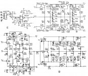
The autobias uses 4xIRF540N 50m Ohm MOSFETs for 4 pair of 2SC5200/2SA1943. Note "m=4" means there are actually 4 pair in parallel. The emitters are not paralleled as in the original TBP-Zero but each pair has its own independent pair of MOSFETs. The first pair has the bias MOSFETs (M3,M4) that feed the autobias spreader and the other 3 pairs are not used for the autobias spreader - they are reasonably matched (from same tube) so follow the first pair closely and so are thermally stable. Also trans-diodes Q17,Q22 are added to allow relatively high 50m Ohm MOSFETs (previously I used 4m ohm MOSFETs)
It's now quite close to a testable autobias SE version. The advantage of autobias is the power transistors do not need close matching for paralleling while still not using any emitter resistors, so I think it can still be called a TBP-Zero. The other advantage is the thermal stability is not critically dependent on the driver transistors thermal linkages and the autobias spreader does not require any thermal linkage. Hopefully bullet proofed with no emitter resistors.😎
The translation says the idle current for Fig.3 TBP-Zero of 150mA per transistor and there are 4 pairs per side so 600mA idle current.
The SE autobias circuit is updated to 4 pairs and 600mA total and driving 4 ohms (since each side of a bridge/balanced amp with 8 ohm load sees 4 ohms).
The autobias uses 4xIRF540N 50m Ohm MOSFETs for 4 pair of 2SC5200/2SA1943. Note "m=4" means there are actually 4 pair in parallel. The emitters are not paralleled as in the original TBP-Zero but each pair has its own independent pair of MOSFETs. The first pair has the bias MOSFETs (M3,M4) that feed the autobias spreader and the other 3 pairs are not used for the autobias spreader - they are reasonably matched (from same tube) so follow the first pair closely and so are thermally stable. Also trans-diodes Q17,Q22 are added to allow relatively high 50m Ohm MOSFETs (previously I used 4m ohm MOSFETs)
It's now quite close to a testable autobias SE version. The advantage of autobias is the power transistors do not need close matching for paralleling while still not using any emitter resistors, so I think it can still be called a TBP-Zero. The other advantage is the thermal stability is not critically dependent on the driver transistors thermal linkages and the autobias spreader does not require any thermal linkage. Hopefully bullet proofed with no emitter resistors.😎
Attachments

Hi,Hi All,
The translation says the idle current for Fig.3 TBP-Zero of 150mA per transistor and there are 4 pairs per side so 600mA idle current.
The SE autobias circuit is updated to 4 pairs and 600mA total and driving 4 ohms (since each side of a bridge/balanced amp with 8 ohm load sees 4 ohms).
View attachment 1032822
The autobias uses 4xIRF540N 50m Ohm MOSFETs for 4 pair of 2SC5200/2SA1943. Note "m=4" means there are actually 4 pair in parallel. The emitters are not paralleled as in the original TBP-Zero but each pair has its own independent pair of MOSFETs. The first pair has the bias MOSFETs (M3,M4) that feed the autobias spreader and the other 3 pairs are not used for the autobias spreader - they are reasonably matched (from same tube) so follow the first pair closely and so are thermally stable. Also trans-diodes Q17,Q22 are added to allow relatively high 50m Ohm MOSFETs (previously I used 4m ohm MOSFETs)
It's now quite close to a testable autobias SE version. The advantage of autobias is the power transistors do not need close matching for paralleling while still not using any emitter resistors, so I think it can still be called a TBP-Zero. The other advantage is the thermal stability is not critically dependent on the driver transistors thermal linkages and the autobias spreader does not require any thermal linkage. Hopefully bullet proofed with no emitter resistors.😎
Thanks for sharing all these. Helps a lots for understanding this monster(I think)
Do you think it is possible to replace IRFPs with V-FETs like 2SK60, THF51 or LU1014D?
We know that discrepancy of V-FET is larger that modern FETs, but the auto-bias idea you proposed seems making it possible to use less-matched power transistors.
I think it would be great to design a TBP-Zero-VFET, it will definitely be legendary, as the circuit topology and components used are unique and dedicated.
Regards,
Jens
Hi Jensenhoffman,

The LU1014D is a trench SIT/JFET that I model using the VDMOS. The standard n-JFET does not model the static feedback effect (Mu) of the LU1014D - trying to add Mu to the JFET with a VCVS fails due to a wrong voltage to the gate diode. The VDMOS with an appended VCVS works (it's not part of the amplifier just a model trick). (Attached is a model file showing various options for modelling the LU1014D SIT).
To get the LU1014D to sense the current in the BJTs for the autobias loop the LU1014D needs to be biased with -1.3V which is about 350mV above its threshold voltage. The autobias feedback is set so 350mV is developed across each of the 4 LU1014D's giving a total idle current of 660mA (165mA each LU1014D+BJT). This can deliver 10A peak (see plot below):

Above: LU1014D temperature is stepped from 25C (cold) to 45C (hot). The idle current increases slightly (130mA) from cold to hot due to the drop in threshold voltage of the LU1014D (using the datasheets temp-co of -2.6mV/C). And this is without any thermal feedback for the bias circuit (and does not include the compensation from the driver transistor temp-co). Bench tests would be needed to check these temp-co's to see if this is feasible (ie no additional thermal feedback). It looks do-able.
Unfortunately the LU1014D went out of production and as far as I can see there are no similar trench JFET/SIT devices in production now. Does anyone know of something similar that's in production now?
But the LU1014D's would need matching for threshold voltage if they all share the same 1.3V offset voltage.
OR each LU1014D's offset voltage can be trimmed manually at setup (eg 6 trimpots). A practical offset voltage generator circuit has not been worked out yet (this is just to show feasibility). One option is a dual PV converter (eg VO1263) to give the isolation from the +/-9V supply.
BTW Some bench tests have been done for an autobias MOS-diode output stage in this thread https://www.diyaudio.com/community/...ching-auto-bias-power-amp.375141/post-6997567.
Thanks for your suggestion. Yes, see below (and attached files) using LU1014D in place of MOS-diodes.Do you think it is possible to replace IRFPs with V-FETs like 2SK60, THF51 or LU1014D?
The LU1014D is a trench SIT/JFET that I model using the VDMOS. The standard n-JFET does not model the static feedback effect (Mu) of the LU1014D - trying to add Mu to the JFET with a VCVS fails due to a wrong voltage to the gate diode. The VDMOS with an appended VCVS works (it's not part of the amplifier just a model trick). (Attached is a model file showing various options for modelling the LU1014D SIT).
To get the LU1014D to sense the current in the BJTs for the autobias loop the LU1014D needs to be biased with -1.3V which is about 350mV above its threshold voltage. The autobias feedback is set so 350mV is developed across each of the 4 LU1014D's giving a total idle current of 660mA (165mA each LU1014D+BJT). This can deliver 10A peak (see plot below):
Above: LU1014D temperature is stepped from 25C (cold) to 45C (hot). The idle current increases slightly (130mA) from cold to hot due to the drop in threshold voltage of the LU1014D (using the datasheets temp-co of -2.6mV/C). And this is without any thermal feedback for the bias circuit (and does not include the compensation from the driver transistor temp-co). Bench tests would be needed to check these temp-co's to see if this is feasible (ie no additional thermal feedback). It looks do-able.
Unfortunately the LU1014D went out of production and as far as I can see there are no similar trench JFET/SIT devices in production now. Does anyone know of something similar that's in production now?
Yes, the autobias loop removes the need for close matching of power transistors as mentioned in the TBP-zero article since each BJT has its own LU1014D as a FET-diode in series with each power transistor emitter (don't be fooled - m=4 simplifies the schematic - there are actually 4 pairs in parallel and 8 LU1014D's)....the auto-bias idea you proposed seems making it possible to use less-matched power transistors.
But the LU1014D's would need matching for threshold voltage if they all share the same 1.3V offset voltage.
OR each LU1014D's offset voltage can be trimmed manually at setup (eg 6 trimpots). A practical offset voltage generator circuit has not been worked out yet (this is just to show feasibility). One option is a dual PV converter (eg VO1263) to give the isolation from the +/-9V supply.
BTW Some bench tests have been done for an autobias MOS-diode output stage in this thread https://www.diyaudio.com/community/...ching-auto-bias-power-amp.375141/post-6997567.
Attachments
Oops, my LU1014v model should have used "Temp1" and not "Temp" so the current increase with 20C change in the LU1014D now increases by 300mA -- probably thermal runaway! So add two 100R NTC thermistor's in place of R32, R33 and mount them on the LU1014D legs (R32 drain M1 and R33 source M2) for a tight thermal coupling. Reduce R14 to 330 ohms to get zero temperature coefficient. R39 R40, R42 are then changed for the same idle current (670mA). The attached "TC" file is now thermally stable with heating of the LU1014D's.
Attachments
"Do you think it is possible to replace IRFPs with V-FETs like 2SK60, THF51 or LU1014D?"
Why would you want to use expensive unobtaniums as thermal compensation element ?
Patrick
Why would you want to use expensive unobtaniums as thermal compensation element ?
Patrick
May i suggest that you do it KICAD instead. KICAD is open source without limits, and it is actually better.Hi folks,
Not sure if this is the first BUILD thread, but I am sure there's very limited discussion about this power amp.
TBP-zero is a class A amp design without emitter resistors, fully-balanced architecture, and looks very complex to build. I've never build class A without emitter resistors, this is a new challenge.
Thanks to my friends, D.L. and Luke Chu, they help with simplifying the design, making it easier to build and more DIY-friendly. The fully-balanced symmetrical design is modified into single-ended, that means half of materials and cost!
The project will be open-sourced, and Eagle sch and .brd files would be published later for further discussion.
Please be noted that some details on the magazines will conflicted.
Any suggestions are welcomed. 😉
Also i would not run without emitter degeneration or basis resistor on the transistor, or they WILL oscillate with even small capacitive loads.
- Home
- Amplifiers
- Solid State
- TBP-Zero Class A: Research and build