You called it. BW is hotter up top and favors some particularsHave yet to spend any time with the paraflex and all its iterations as at the time seemed a whole lot of effort for getting a bit more over a narrower BW up high.
OK, so multi-tapping a BAWC? IIRC B0$3 has a patent for this and/or took over one when its patent ran out.
Regardless, got a lot on my 'plate' these days, so basically just responding by rote when I can, really don't have time/energy for 'brain teasers'.
Anyway, hope you get it all worked out and assume you'll have to use AkAbak to sim it.
GM

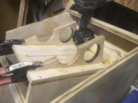
Attachments
And a similar with a longer kerfed exit in the garage
OK, assuming a 1/4 WL offset, this is essentially a Danley DTS concept TH.
GM
Its so incredibly loud theres no need to not grab gentler and lower just ‘because’.
Yeah, 'flat' in a typical room = boombox and why historically I've preferred/recommended extended BW [EBS] alignments.
GM

OK, assuming a 1/4 WL offset, this is essentially a Danley DTS concept TH.
GM
I think so? Im not sure which Danley but ‘tower of power maybe?
Starts at center of the bisecting box panel in the tapped entry, then is sent to a closed, where it goes all the way to the other end of a fold and makes another trip to the drivers motor side tap and has the rest to travel til the exit
That as
(driver(-)), 80 cm, (then fold), 160 cm, (then fold), 80 cm (then (driver(+)), then 80 cm (exit).....
But theres other lengths that can fit than... hmmmmm
I ve got to plot that out as frequency, fillter LP, freq, filter LP, freq, polar shift, freqency , polar shift. the ladt two ‘polar shift affect all frequencies not just LP filter. Or thats whats suggested to me by the sim...
Last edited:
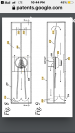
DTS concept TH patent, [DTS-20 fold shown]: US8457341B2 - Sound reproduction with improved low frequency characteristics
- Google Patents
DTS-10 fold: danley dts-10 - Google Search
- Google Patents
DTS-10 fold: danley dts-10 - Google Search
I owe you about 6 hours of good reading material now. And rising! that link drops right i to a plethora of speaker patent goodness! Thx!

Why are simulation pics posted sideways?
Cheers!
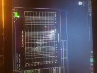
View attachment 906942
View attachment 906943
The black curve is the 120 + 120 + 80 cm tapped pipe version.
The grey curve is used as a reference and is 20 + 278 + 22 cm. Both have a 600 cm2 CSA and both use the same Beyma 15 inch driver.
What am I missing here (or what have I got wrong)???
I think i finally figured this all out. And its probably confused a lot including me😱 the idea of building on the harmonics is a great one. Thanks to Greg over and over again, and quite a few people in the qw section of the FB tech groups including paraflex and MLTL, and USRFObijuan i was able to chase down a few things and even managed to put together some great crash test dummies🙂
it seems the pattern i was insistent on can be found in ‘tower of power’, and some folded bose wave can on ideas too. theyre still pretty tricky to incorporate in a design because of fording and turns eating the math that you need to be both standingwaves AND an overall Fb(CSA expansion too).
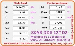
Also, with just a bit of sizing to dampen, ive found it possible to routinely get this $159 @ amazon driver to pair up (12”) and sim quite nicely in anything 18ds115. thanks to ‘Phil’ for sharing lots of bis 18ds115 info!!
Guerilla, the phone sometimes is in potrait mode and sizes a square otherwise i think. Sorry bud. I just realized that.
Anyone with any great 18ds115 plans willing to share. I like to transfer them imto this economical option if they fit as a sortof geek nerd hobby thing for speakers🙂 and so $550 isnt the only option? Its a challenge too. Its tricky sometimes..
Now to make a SKAR ddx12 tower of power sim🙂
https://www.amazon.com/Skar-Audio-D...dchild=1&keywords=Ddx12&qid=1609797337&sr=8-1
This thing is $128 on holidays too
This thing is $128 on holidays too
Attachments

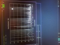
View attachment 906942
View attachment 906943
The black curve is the 120 + 120 + 80 cm tapped pipe version.
The grey curve is used as a reference and is 20 + 278 + 22 cm. Both have a 600 cm2 CSA and both use the same Beyma 15 inch driver.
What am I missing here (or what have I got wrong)???
Found a better pic than any of my poor attempts to explain😀 thx to GM!
Danley uses akabak. Apparently he might see the fold or path breakups as LP filtered completely. Where horn response is not being given the info for ‘folding’.
i chased a leakin in a box that didnt exist and trouble shot it by simming (fake) its location in HR to create the same impedance plot. It was actually a folded segment in a very sensitive area do to the shape i used (and some ‘assumptions 🙂 )
i chased a leakin in a box that didnt exist and trouble shot it by simming (fake) its location in HR to create the same impedance plot. It was actually a folded segment in a very sensitive area do to the shape i used (and some ‘assumptions 🙂 )
Attachments
Last edited:
- Home
- Loudspeakers
- Subwoofers
- Tapped out tapped super pipe