Over in the tapped horn thread, I posted a cheap and easy to build tapped horn. I decided to break it off that thread, to keep all the details in one place.
Here's the post:
http://www.diyaudio.com/forums/showthread.php?postid=1383036#post1383036
Here's the post:
http://www.diyaudio.com/forums/showthread.php?postid=1383036#post1383036
Here's a couple of pics of me putting it together:
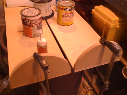
Gluing the end caps

Believe it or not, I had all the sonotubes AND the woofers just sitting in my garage
Gluing the end caps
Believe it or not, I had all the sonotubes AND the woofers just sitting in my garage
Thanks for posting, I read the post in the collaborative thread and found it interesting. Keep us informed!
I thought your were going to put this together in an hour 🙂
Seriously though, let us know when you have this project up and running, .. I have two of those MCM drivers working in different "Tuba" horns.
Seriously though, let us know when you have this project up and running, .. I have two of those MCM drivers working in different "Tuba" horns.
zobsky said:I thought your were going to put this together in an hour 🙂
Seriously though, let us know when you have this project up and running, .. I have two of those MCM drivers working in different "Tuba" horns.
I built a clone of the Autotuba too. That's a fun sub box. Used it in my old Accord for about six months. When I bought a new one I made a new sub, using the same driver, but tweaked it so that it would play deeper.
Because the Autotuba's response falls so quickly, it has a lot of "slam" and efficiency, but lacks the deep bass that carfi guys know so well. You might get the best of both worlds if you used EQ to "cut" the midbass though. I was a bit concerned about frying the driver, because I was feeding it about 800 watts! (it's rated for 100 IIRC 🙂
Bad news - I had second thoughts about the viability of this, so I went back to the drawing board.
Good news - I solved the problem.
Here's how I did it.
Anytime you're building a horn, you're juggling a bunch of variables. If you want efficiency, you have to sacrifice extension. If you want to make it smaller, the response gets ragged. You can smooth the response with careful use of a taper, but that makes the box harder to build.
Building horns is tricky.
In the design I posted, with a single woofer, I felt the response was too ragged. It was easy to build, but I was worried it wouldn't sound good. I tried fixing that by reducing it's efficiency. Reducing the efficiency smooths the response of a horn. I reduced the box efficiency by adding a second driver in the same horn, basically halving the airspace for each one. That worked well, but the efficiency wasn't much better than a bandpass.
Then I tried a trick Dan Wiggins recommends. I added a resistor to the circuit, which raises the QES (and the QTS.) That worked great! By raising the QTS FROM .24 TO .60, the response of the tapped horn was much smoother. Of course efficiency suffers, but I'll take smooth response over efficiency any day! Another bonus is that you could adjust the QTS value by changing the resistor value. Even better, this gives me an easy load for my amp to drive, which is particularly important since I intend to use three or four subwoofers (per Geddes.)
The resistor value is five ohms; I intend to use two 10ohm resistors in parallel, which you can get from any ol' Radio Shack.
In case anyone's curious, here's how you model the size of the resistor.
http://www.diysubwoofers.org/dipole/design.htm
To increase the Qts to the target value, we can use a series resistor Rs, and calculate its value as follows:
Qes'=Qts'*Qms/(Qms-Qts')
Qes' = 1.75*7/(7-1.75)
Qes' = 12.25/5.25
Qes' = 2.33
Rs = Re*(Qes'-Qes)/Qes
Rs = 2*(2.33-1.30)/1.30
Rs = 2*1.03/1.30
Rs = 1.6 ohms
As we plan to drive the system with 100W of power, assuming 10:1 differences between average and peak levels, we can use a 10W or greater resistor for Rs.
Here's the math for figuring out the resistor with the MCM speakers. In a nutshell you need a 5.67ohm resistor - I just rounded down to 5ohm since they're easy to find at
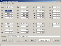
First, here are the specs of an MCM 55-2421:
John Krutke posted these specs a few years back; I have personally measured half a dozen of my woofers, and they're in sync with his measurements.
Fs=30.95 hz
Qms=12.2863
Qes=0.2365
Qts=0.2320
Vas=23.88 l
SPL=86.59 1w/1m
Re=3.4
Le=2.42
BL=13.15
Xmax=16mm P-P
To increase the Qts to the target value, we can use a series resistor Rs, and calculate its value as follows:
Qes'=Qts'*Qms/(Qms-Qts')
Qes' = 0.6*12.28/(12.28-0.6)
Qes' = 7.37/11.68
Qes' = 0.63
Rs = Re*(Qes'-Qes)/Qes
Rs = 3.4*(0.63-0.2365)/0.2365
Rs = 3.4*0.3935/0.2365
Rs = 5.657 ohms
Here's my original post, from months ago. NOTE I've modified it to reflect the new design, which is 25% longer. In all other respects, it's identical to my original proposal.
This is my design for a tapped horn using the MCM 55-2421, which I still believe is one of the best horn drivers available. The fact that it's $25 is a bonus.
The goals of this design were different than what a lot of you guys are going for. This one is optimized to be as small as possible. It's also INCREDIBLY simple to build. It's a eight foot tall sonotube, with a plywood divider running down the middle. There isn't even a taper! Because it's efficiency is lower than most tapped horns (about 96db) you don't get a lot of ripple.
I think this tapped horn would be great for car stereo too, but you'd have to come up with a novel folding scheme. (Unless you can figure out a way to squeeze an eight foot long subwoofer into your car!!)
So here's how to build it:
1. Get a 8ft tall sonotube that's 10" across
2. Get a piece of plywood, cut it to 10" x 90"
3. Cut out a 7.5" hole for the woofer. The location of the hole is very important. The centerpoint of the hole must be 18" from the end of your 90" piece of plywood.
4. Put the two MCM woofers in the hole
5. Put the plywood divider right inside the sonotube
6. Cap one end of the sonotube completely. Leave a 5" gap between the end cap and your piece of plywood
7. Put a cap on the other end that covers up one HALF of the sonotube
8. That's it!
Before I post my design I gotta warn ya'.
You guys have seen some of the crazy outrageous I've done - I'm a big fan of crazy waveguide projects that take ages to finish.
But this sub project is S-I-M-P-L-E.
Yes, I could have made it flatter. Yes, I could have made it play lower. But to do that, I would have made it a LOT more difficult to build. And I need at least three of these, and I really don't want to spend my entire Summer building subwoofers.
So...
It's not perfect.
But IMHO, you're not going to find a tapped horn that's easier to build, and you sure as hell aren't going to find a subwoofer that can be built for $50 that can outperform this monster.
Yes, FIFTY BUCKS kids. The driver is $25, the sonotube will set you back about ten bucks, throw in another $15 for wire, wood, carpet and terminals.
FIFTY BUCKS.
IF you want to make it better, go right ahead. Increasing the taper will flatten the response, but will also raise the F3 and make it MUCH harder to build. You can double the power handling by adding a second woofer, but then you'll have to tweak the resistor to lower the QTS of the system.
Without further ado, I present The Tapped Horn for Dummies
Patrick, I tried this a few years ago with 6" plastic pipe & 4" drivers, I put a 'Karlson slot' at the 'output' end. I made the pipes 1.2m high in the hope of getting down to 40Hz.
Now I have a bit more knowledge & a 2m length of 12"pipe, I was thinking of trying again with better drivers.
I'm interested to understand why you see this as a 'tapped horn' rather than a transmission line?
Cheers,
Pete McK
Now I have a bit more knowledge & a 2m length of 12"pipe, I was thinking of trying again with better drivers.
I'm interested to understand why you see this as a 'tapped horn' rather than a transmission line?
Cheers,
Pete McK
Patrick Bateman said:
There isn't even a taper! Because it's efficiency is lower than most tapped horns (about 96db) you don't get a lot of ripple.
This is a tapped PIPE (or TL if you prefer) as I've suggested and shown a few designs of on the tapped horn thread (see links for one of them) and I assume since you put two drivers in one hole that it's an isobaric TP.
As for the ripple, the ones I did sure simmed a lot of HF 'hash', though never having built one I don't know how bad it is in reality.
Note too that Al (pinkmouse) built one I did for him and it performed/measured very poorly, though there seemed to be some question as to how airtight it was, so he was going to get back to us, but that was months ago and he's been MIA on the thread ever since.............
http://www.diyaudio.com/forums/showthread.php?postid=1391597#post1391597
http://www.diyaudio.com/forums/showthread.php?postid=1391598#post1391598
GM
There's a glitch in my post. I went back and forth between using one woofer and two. I'm using ONE woofer for the project.
The MCM woofer is designed for such a tiny box - when you use a single woofer there's a lot of ripple in the response due to this.
The resistor flattens out the response quite a bit by raising the QTS of the woofer. (A higher QTS requires a bigger box or horn.)
The MCM woofer is designed for such a tiny box - when you use a single woofer there's a lot of ripple in the response due to this.
The resistor flattens out the response quite a bit by raising the QTS of the woofer. (A higher QTS requires a bigger box or horn.)
GM said:
This is a tapped PIPE (or TL if you prefer) as I've suggested and shown a few designs of on the tapped horn thread (see links for one of them) and I assume since you put two drivers in one hole that it's an isobaric TP.
As for the ripple, the ones I did sure simmed a lot of HF 'hash', though never having built one I don't know how bad it is in reality.
Note too that Al (pinkmouse) built one I did for him and it performed/measured very poorly, though there seemed to be some question as to how airtight it was, so he was going to get back to us, but that was months ago and he's been MIA on the thread ever since.............
http://www.diyaudio.com/forums/showthread.php?postid=1391597#post1391597
http://www.diyaudio.com/forums/showthread.php?postid=1391598#post1391598
GM
Thanks for the heads up. I was going to build three right off the bat; maybe I'll build one and measure it before I commit to a set.
GM said:
This is a tapped PIPE (or TL if you prefer) as I've suggested and shown a few designs of on the tapped horn thread (see links for one of them) and I assume since you put two drivers in one hole that it's an isobaric TP.
As for the ripple, the ones I did sure simmed a lot of HF 'hash', though never having built one I don't know how bad it is in reality.
Note too that Al (pinkmouse) built one I did for him and it performed/measured very poorly, though there seemed to be some question as to how airtight it was, so he was going to get back to us, but that was months ago and he's been MIA on the thread ever since.............
http://www.diyaudio.com/forums/showthread.php?postid=1391597#post1391597
http://www.diyaudio.com/forums/showthread.php?postid=1391598#post1391598
GM
Well I don't want to build junk, so I did a bit of redesigning. I still want to keep it simple, but integrated a taper by putting the center panel a bit off center. This basically creates two sides of the pipe, one that's double the size of the other.
Voila! Two to one taper.
I also found that Home Depot and Lowes have Sonotubes that are 9.5" in diameter. That's what I'm using instead of ten inch. The reduction in diameter flattens out the response further, since these MCM woofers really want a small box.
Parameters attached.
Attachments
Patrick Bateman said:
The resistor flattens out the response quite a bit by raising the QTS of the woofer. (A higher QTS requires a bigger box or horn.)
Yeah, there's 'no replacement for displacement' down low and it takes a minimum box size for a given ~flat gain BW, so either Vas or Qts must go up to 'fill' it if you want it ~flat, with increasing the latter being the easiest for the DIYer.
GM
Patrick Bateman said:
Thanks for the heads up.
Well I don't want to build junk, so I did a bit of redesigning. I still want to keep it simple, but integrated a taper by putting the center panel a bit off center. This basically creates two sides of the pipe, one that's double the size of the other.
Voila! Two to one taper.
You're welcome!
I didn't mean to scare you off as I don't see anything fundamentally wrong with the TP concept and apparently the math doesn't either according to Hornresp, just that Al's build highlights how sensitive to variables any tapped pipe/horn build can be and unfortunately he hasn't let us know where his might have gone awry.
I'm still probably up to at least a year away before I'll be set up to build/measure again, so was hoping someone in the meantime would give these a shot since they are so cheap/simple to build.
If I'm understanding you, the baffle is just made narrower and offset to create a stepped pipe rather than the tapered one simmed, so it will be interesting to see how it measures Vs the sim.
Anyway, thanks for sharing as so far outside the few on the TH thread that have taken the 'plunge', folks I've suggested THs to have proven way too intimidated by such simple box builds once one or more internal angled boards are added. 🙁
Maybe if we call them shelf braces instead..............
GM
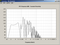
Patrick Bateman said:frequency response
John
That just looks like a badly tuned bandpass. Why not just build a bandpass? They have worked well for me.
- Status
- Not open for further replies.
- Home
- Loudspeakers
- Subwoofers
- Tapped Horn for Dummies