I did go at it again, though this time with two drivers, which leads to a question...
If I have this in Hornresp, that is two drivers in series (or parallel) shown here as TH set to 2S...

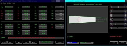
...does that mean I can build it like this, that is with two drivers spaced along the LENGTH of the horn? Below is a cross-section view of the horn design that matches the Hornresp sim.

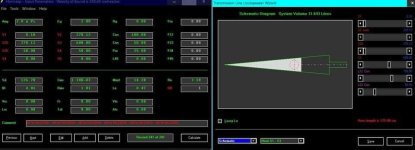
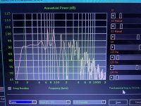
If so then this design will work... There is some headroom to EQ that dip at 40Hz. With a little damping there is a nice rolloff at the upper part of the bandpass range. I have room for this as huge as it is (about 2' x 2' x 8') and it won't take a ridiculous amount of wood to build. Here is the response, which is massive.

If I have this in Hornresp, that is two drivers in series (or parallel) shown here as TH set to 2S...
...does that mean I can build it like this, that is with two drivers spaced along the LENGTH of the horn? Below is a cross-section view of the horn design that matches the Hornresp sim.
If so then this design will work... There is some headroom to EQ that dip at 40Hz. With a little damping there is a nice rolloff at the upper part of the bandpass range. I have room for this as huge as it is (about 2' x 2' x 8') and it won't take a ridiculous amount of wood to build. Here is the response, which is massive.
Last edited:

I suggest measuring the t/s parameters of those drivers before committing to any designs.
I'd also avoid using a driver with highish Qts (>0.4) and low Vas in any type of TH.
I'd also avoid using a driver with highish Qts (>0.4) and low Vas in any type of TH.
PE had some issue with their supplier for the UM line making undocumented changes that affected the published specs, seemingly by quite a bit. The linked thread is for the 18" but I think remember reading something similar for the 15" a few years back.
https://techtalk.parts-express.com/...-t-s-parameters-way-off?p=1499613#post1499613
What you actually have, and what application they'll work best with likely depends on when your drivers were manufactured.
https://techtalk.parts-express.com/...-t-s-parameters-way-off?p=1499613#post1499613
What you actually have, and what application they'll work best with likely depends on when your drivers were manufactured.
Is it better to eq the peaks away or to fill in the dipI did go at it again, though this time with two drivers, which leads to a question...
If I have this in Hornresp, that is two drivers in series (or parallel) shown here as TH set to 2S...
View attachment 1241781
...does that mean I can build it like this, that is with two drivers spaced along the LENGTH of the horn? Below is a cross-section view of the horn design that matches the Hornresp sim.
View attachment 1241784
If so then this design will work... There is some headroom to EQ that dip at 40Hz. With a little damping there is a nice rolloff at the upper part of the bandpass range. I have room for this as huge as it is (about 2' x 2' x 8') and it won't take a ridiculous amount of wood to build. Here is the response, which is massive.
View attachment 1241785
Yes....does that mean I can build it like this, that is with two drivers spaced along the LENGTH of the horn?
Or cut the peaks, the result is the same, as long as the drivers are not exceeding Xmax.If so then this design will work... There is some headroom to EQ that dip at 40Hz.
+/-2.5dB 22-90Hz is quite good for a TH.
Brian Steele - Agreed I get that this is a square peg in a round hole type situation but that is the point of the exercise for me, to figure out if it is feasible or just too far off of ideal to work practically.
I do not have the equipment, at least not yet, to make TS measurements. I know the manufacturers being off can be an issue. That's a downside to THs I suppose... They are more sensitive to variations in driver specs compared to say a sealed.
I agree cutting the peaks or lifting the dip would accomplish the same thing more or less as long as xmax is not exceeded (as stated). I would say that is more of a DSP based choice depending. With a 125-130 dB response at xmax, and relatively low power requirement, the head room is there. That is far more power than I would need normally.
BTW I noticed the UM15-22 drivers are on sale right now at PE if anyone cares.
Any thoughts on the driver placement? From what I have read others have done this in similar designs with success. AFAIK there is not a way to model this directly in Hornresp.
Question:
If you model the variety of driver entry positions in qw resonators you find the locations that remove one of the other resonaces And extend the bandwith through a former cancelation just above that.
Otherwise why would we want to ‘offset’ the drivers ? ‘Maybe Some air mass/pressure on either side of the cone(s) helps it from wobbling or scraping on the voice coils?
i recently goofed up a voice coil and suspected this might have been the issue?
Attachments
Never mind, found it in another thread here. Hornresp 'takes care' of using two drivers. The S2 point is placed on the centerline between the two speakers, which is how I have modeled it.Any thoughts on the driver placement? From what I have read others have done this in similar designs with success. AFAIK there is not a way to model this directly in Hornresp.
In this case I am only doing it to fit two drivers into the same horn enclosure for more output at xmax. The point here is that when modeling it in Hornresp, as long as the drivers are close to and equally spaced on either side of the S2 point then Hornresp will model it correctly enough.Question:
Otherwise why would we want to ‘offset’ the drivers ?
To your point, yes I have heard about asymmetric pressure on the cone surface causing misalignment that results in damage. AFAIK that has not happened to me personally. I've melted voice coils but that's a different problem. 🙂
Driver placement is technically a function of its effective upper mass corner (Fhm = 2*Fs/Qts') at each end (TH) or one end with the other at its effective 1/4 WL (DTS). What folks seem to fail to realize is that all vented box speaker alignments are fundamentally based on this math:
T/S max flat alignment:
Vented net volume (Vb) (L) = 20*Vas*Qts'^3.3
(Ft^3 = (Vb)/~28.31685)
Vented box tuning (Fb) (Hz) = 0.42*Fs*Qts'^-0.96
F3 (Hz) = Fs*0.28*Qts'^-1.4
The box only loads the driver to its upper mass corner (Fhm):
Qts': 2*Fs/Fhm
Fhm = 2*Fs/Qts'
Fs: Fhm*Qts'/2
(Qts'): (Qts) + any added series resistance (Rs)
True, so use the max flat math to find the tuning and you'll flatten them.......... Indeed, noting this dictum I've periodically posted:I think that’s a lack of motorforce and quite a high Qts so you’re just left with those ringing peaks at the two QW resonaces? What if you stretch one of those home theatre ported boxes for the ultimax into a tapered tapped pipe ? (I think they’re called ‘Marty’?
While the 'sweet spot' (mean) is a ~0.4412 Qts', a 'close enough' simple guideline is:
~0.403, Vb = Vas, Fb = Fs (constant tapered MLTL)
~ <0.403, Vb = < Vas, Fb = > Fs (inverse tapered MLTQWT)
~ >0.403, Vb = > Vas, Fb = < Fs (expanding taper MLTQWT/MLhorn)
Keeping in mind that one has to factor in the (huge) impact thermal power, inductive distortion can have on effective Qts, the dominant vented box alignment factor.
What is a ‘constant’, as opposed to the ‘inverse’ and ‘expanding’ taper? Is it just a stepped reduction instead of the horn/cone shapes?
(constant is the one I don’t know how to create/design/draw)
(constant is the one I don’t know how to create/design/draw)
Attachments
Based on the above and latest high Qt specs, this is what I get; a whopping big 800+ L box with a ~120 dB/16 - 110 Hz/800 W/2pi
Note that I see no worthwhile DTS variant, though reducing the CR to 2:1 yields a ~754 L box, rolled off < ~21 Hz trade-off. Not many 'free lunches' in audio design. 🙁
Note that I see no worthwhile DTS variant, though reducing the CR to 2:1 yields a ~754 L box, rolled off < ~21 Hz trade-off. Not many 'free lunches' in audio design. 🙁
Attachments
Last edited:
'Constant' as in constant cross sectional area = no taper, just a long box/tube.
Monster!Based on the above and latest high Qt specs, this is what I get; a whopping big 800+ L box with a ~120 dB/16 - 110 Hz/800 W/2pi
Attachments
Interestingly enough the design I came up with in WinISP for a BR is also about a 800L enclosure.
Thanks GM and everyone else for the input.
Thanks GM and everyone else for the input.
You're welcome! Yeah, it takes 'x' minimum amount of net Vb for a given output no matter the shape, hence I always start with the basic math to see where I'm at............
- Home
- Loudspeakers
- Subwoofers
- Tapped Horn Design for UM15-22