Have you guys ever considered the following possibility:
All organs run on blowers. Large motors turning a large fan. The are actually a type of compressor the fan is a rotary vane type. Not the normal push air around type fan.
Anyone that has been around a pipe organ knows the feeling of the blower running and not running.
That blower noise is almost certainly the ultra low frequency content in the measurement.
All the comparison in the world will not get to the nit of the issue regarding what has been measured.
We have a measurement and we have the measurement conditions stated.
From here we have to think. Not dissect to make our own points.
Take as much information as you can from the knowns and make sense of it.
Pertaining to the iNuke. I think there is a way to do what is required.
It is a little trick in the parametric EQ settings if it is similar to the DSP that I have worked with.
I'll have to look.
Out for a while.
But I'll be back.
Arnold Black Person
The measurement was the signal straight of the Artisan, so if it was blower noise it was noise that was included in the recorded sample, not from OP's organ.
Anyway, this is the first measurement OP ever made and there's no way to know all the measurement conditions and settings on his computer or on the Artisan so this measurement could be showing absolutely anything. Can you explain the lack of harmonics? Didn't OP already say he eq'ed the Artisan ouput? Do you know what type of processing OP has applied or what the Artisan signal is supposed to look like?
I'm not saying it was a bad measurement, I'm just saying we don't know if it's a good measurement, and putting too much stock in this measurement of unknown quality would be pretty stupid. It might be accurate, it might not.
To be clear, there are no "knowns" about this measurement. It looks like it could be within the realm of possibility but it's definitely not what anyone was expecting to see, so exercise some caution here. It's a good first step, but that's about all it is.
Last edited:
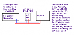
My Test suggestion
The intention is 2 things.
1st - To compare & see what happens in the laptop, when sine waves of between say 10Hz - 20Hz are applied from a Hardware FG, rather than tones from Artisan etc. Using a software FG means routing through a LT's Output capacitors, which might not give a flat response down to 10Hz & below !
2nd - Also to discover the Actual laptops fr @ low frequencies, to see if it is flat or rolls off due to it's Input capacitors.
That's what i would do, & have done when testing/installing sound systems etc.
Attachments
Good observations by JAG and Zero D.
As to the blower - these samples were from another pipe organ. That organ would have to have a blower too. Without questioning the person who recorded the sounds, it would be difficult to know what was being recorded.
I have used REW before while testing our homemade boxes. I used the Dayton microphone to make some measurements. But I freely admit that I do not consider myself fluent with REW. I'm a little more comfortable with TruRTA. But I understand that REW is considered to be "the accepted standard" by most people in this forum.
I THINK I may be able to do the testing Zero D has suggested, though it may have to wait until after this weekend. Easter Sunday is a biggie for me.
I will check out some of the iNuke links and forums (fori).
I repeat my thanks for the thoughtful consideration from all.
Bach On
My recommendation would be to get the signal chain in order first so that you have proper signal strength. This shouldn't require any measurements of any kind.
At that point you can start measuring stuff. There is no "accepted standard" measurement package, just make sure it has proper resolution to be useful and make sure you post screen shots of the measurements so everyone can view them.
Make sure the signal chain is flat (no "notelevel" eq, no dsp, no other tricks either in Artisan OR the measurement software OR the computer itself) and measure what you can at different points in the signal chain. Explain in detail exactly what (like what note), how you measured and why.
At that point it would be nice if you could do frequency response measurements with a mic.
Just a quick story to show how helping from a remote location can be a problem with respect to what a person is ACTUALLY doing vs what you ASSUME he is doing.
I worked in telephone tech support for a couple of years. An old guy called because his printer wouldn't work. There's only so many things that can cause it to be completely unrecognized so the troubleshooting steps were simple and we went over them DOZENS of times for a couple of hours.
My shift ended and a supervisor continued for ANOTHER two hours. The problem ended up being that he was plugging his usb printer plug into an ethernet port.
Even after I (and the supervisor) had told him to make sure he was plugging in properly at least several dozen times, he wasn't. And there's no way to help with that because you can't see what he's doing until he realizes his own mistake.
Such can be the problem with trying to help with any issue from a remote location.
Ben assumes the measurement is garbage. Mark seems to think it is a fine measurement. I have no idea, it looks funny but it could be plausible. There's no way to know without being there. There's probably at least a couple dozens settings in the signal chain, the measurement software and the laptop that can affect things. No one can know what's going on except the OP and if he isn't experienced even he doesn't know.
So let's take it easy and work on basics.
"The bad news is that the lowest frequency for the software is 20 Hz., since that is the lowest listed frequency for the amp. There are several types of crossover parameters that can be set for EQ, such as Linkwitz, etc. "
Choice of EQ and crossover paradigm hardly matters even for folks with electrostatic loudspeaker systems (ahem, ahem) and not at all whatsoever for your organ.
"20 Hz" is just a cliche used by the marketing department. Might bear only slight resemblance to hardware realities.
If you do a single REW frequency run, in 15 seconds you'll find what the true low end slow rolloff is (and high end and distortion and noise and headroom) of the Behringer. Or you could fret and post about it for weeks.
Likewise, if you do the RTA on your lowest pedal, likewise in short order you'll find out what kind of content (musical and otherwise), if any, you have below 20 Hz.
Your system is complicated. Each additional piece of gear adds garbage to the sound* even if serving some otherwise useful purpose (or not). All the more reason to eyeball the signal at the tone generator and then at the end and, if needed, then in the middle.
Ben
*not exactly true when running digital signals across a few pieces of gear
Last edited:
Hi Y'all,
You have been busy. 🙂 Just a note: I have to agree w/ just a guy, Post #584: "...get the signal chain in order first so that you have proper signal strength...", additionallty, this is the stage where you want to carefully measure signal strength v. signal frequency preferably at all stages in the signal chain. At least you have to know the input voltage v. frequency at the speaker input terminals, otherwise what are you measuring w/ your mike?
Here are two additional aps I like, which may come in handy:
- for quick tone and level checks Darkwood Audio Test Generator ( Test Generator ), and
- to set up complex tones, sweeps, loops look at NCH Tone Generator ( Tone Generator Software ? Sound Frequency & White Noise Generator (PC or Mac) )
both can be downloaded for free.
Regards,
Hi All,
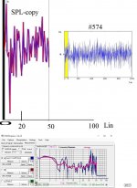
FYI: An Observation of the Picture in Post#574:
b🙂
There's no marking except a single zero on the vertical axis of that white noise graph so it could easily be 0.01 db down or 130 db down at 16 hz just as easily as 23 db.
What is that? Do I see the familiar 34 Hz organ note? And just noise below? Or 340 Hz?
B.
Bjorno took the white noise picture, made an .frd file (based on wholly made up spl levels it seems) and input the .frd into Holm Impulse, a measurement program.
No it's not a 34 hz organ note, it's white noise plotted from a picture and input into measurement software.
Clearly you don't know what you are looking at. At all.
"The bad news is that the lowest frequency for the software is 20 Hz., since that is the lowest listed frequency for the amp. There are several types of crossover parameters that can be set for EQ, such as Linkwitz, etc. "
Choice of EQ and crossover paradigm hardly matters even for folks with electrostatic loudspeaker systems (ahem, ahem) and not at all whatsoever for your organ.
"20 Hz" is just a cliche used by the marketing department. Might bear only slight resemblance to hardware realities.
If you do a single REW frequency run, in 15 seconds you'll find what the true low end slow rolloff is (and high end and distortion and noise and headroom) of the Behringer. Or you could fret and post about it for weeks.
Likewise, if you do the RTA on your lowest pedal, likewise in short order you'll find out what kind of content (musical and otherwise), if any, you have below 20 Hz.
Your system is complicated. Each additional piece of gear adds garbage to the sound* even if serving some otherwise useful purpose (or not). All the more reason to eyeball the signal at the tone generator and then at the end and, if needed, then in the middle.
Ben
*not exactly true when running digital signals across a few pieces of gear
Again you have no idea at all what you are talking about. The Inuke has built in dsp which is very similar to the dsp built into the Behringer DCX or DEQ or whatever you own yourself.
The 20 hz referred to here is the lowest frequency the dsp addresses. It's not a "cliche used by the marketing dept", it's actually proven to be pretty accurate. This stuff has been measured by lots of 3rd party users.
This stuff is very clearly over your head, in the last two posts alone you have shown that you don't have any idea what you are even reading. You are just adding confusion to some pretty straightforward and simple topics.
Unless I'm misunderstanding the concept of white noise (which is possible since the math is beyond me) it doesn't have a strictly set amplitude so unless it's marked on the graph you don't know what spl level it is.
And it's random, meaning it could just as easily been a positive value at 16 hz (in relation to 0 hz) just as easily as what was shown, the negative value at 16 hz in relation to 0 hz.
And it's random, meaning it could just as easily been a positive value at 16 hz (in relation to 0 hz) just as easily as what was shown, the negative value at 16 hz in relation to 0 hz.
Hi JAG,
Wikipedia has a nice article on the colors of noise: https://en.wikipedia.org/wiki/Colors_of_noise , and they have more in depth treatments of the individual signals. On some signal generators you can set the crest factor of the noise in addition to the type of noise, additionally the noise can be bandwidth limited, e.g.: third octave...
Regards,
tb46 (Oliver) has (I believe) suggested measuring the voltage and frequency at each stage of the signal path. Voltage would be measured with an RMS meter. I do have one - though it is an older Radio Shack model. It is digital, so it would provide specific numbers.
I think I'm looking at something like this: (feel free to correct the individual steps - or the order in which I should perform them.
1. I need to use a signal generator to produce individual frequencies and measure them with REW. This is to get a sense of the frequency response of the laptop computer. I should also measure the signal voltage coming from the signal generator using the VOM.
2.. I should do measurements with the VOM (set for AC) the signal from the Artisan output jack. Then each note I want to measure (particular the lowest notes for for the 32 foot stop) should be measured using a program like REW. One note for something like 5 seconds might be about right.
3. Step 2 should be repeated on the signal from the Samson preamp when I finally get it and add it to the signal path.
4. I should then check the speaker output from the iNuke amp. Here things get a bit fuzzy for me. I'm guessing the using the VOM to measure the voltage would be OK if the meter voltage range was set high enough. But a direct input through the laptop computers Line In jack would probably be too high.
5. Finally, the microphone should be used to measure the sound coming from the speakers. This should probably be done in three stages.
a. the box with the 18 inch driver
b. the box with the two 15 inch drivers
c. both boxes playing at the same time.
Oliver has suggested a couple of free programs I should consider getting. JAG has suggested Audacity. I'll look into those.
I'm going to make a MIDI file which will be used to play the notes I plan to measure. I need to be at the laptop computer and meter to do the measurements. I have another laptop computer that can play the MIDI file through the organ for the notes I want to measure.
That should keep me busy. AND it may provide data that might better shed light on the frequencies and voltages within our system..
Feel free to correct or recommend different steps. I'd like to do this somewhere near close to correctly.
Bach On
Audacity is what I use to check frequency response of mp3 and WAV files. If you don't have recorded mp3 or WAV files I'm not sure what Audacity would do for you.
I'm actually not too sure what else Audacity does, I don't use it for much except a couple of very specific purposes.
All this checking voltage seems unnecessary to me. You can do it if you want but first answer two quick questions.
Does the inuke have input clip lights?
Are you able to light them up?
If you can't light up the input clip lights (if there are input clip lights) you need to get the DI box in the signal chain because you input signal is most likely not nearly strong enough.
A quick look at a random Inuke Quick Start Guide shows it has Signal and Limit LEDs.
display the signal level for each channel. Reduce the input gain if the red limit LED lights up continuously.
That sounds like an input clip light to me. Is it lit up red continually (or at all - like ever)? Is the red limit LED the only one or is there a "regular" input LED that's like green or something? Are you lighting that one up?
There are really really easy ways to figure out your signal strength. You can go ahead and measure everything you like, but if you are not able to light up your signal lights that's the first issue that needs to be addressed, and you don't need to measure anything to figure that part out.
Is the Artisan output flat? (No notelevel eq.) What else is in the signal chain before the amp?
Get your ducks in a row before you start going on a measurement crusade. Seriously, looking at what the amp lights are doing is a lot easier than measuring and will tell you what you need to know at this point.
Once you have a good strong signal and everything in the signal chain is set to flat (no note boosting or dsp or eq of any kind) then you can start measuring the signal itself with REW.
"The cowboy saddled his horse and ran off in all directions"
Here are questions you should try to answer to start with.
1. What is the frequency range I need to handle? Look at the REW RTA of the tone generator when playing the lowest pedal.
2. What is the sound resulting from that note? Look at the REW RTA of a mic and see how it compares to the tone generator signal.
If you start that way, you are heading in the right direction.
Oddly, max loudness (or even just estimating headroom) is very tricky to establish without a lot more sophistication because of the risk of breaking stuff. Don't worry about it for now.
Better to use a key or pedal, not the midi, because that introduces all kinds of "unknowns" in the process.
Don't use an RMS meter on your tone generator output or downstream - they aren't useful except for clean sine waves. But if you have an uncontrollable urge, REW has good signal generator and flexible meter ("SPL Meter") built in.
Ben
Last edited:
Ramblin' Man
Hi Bach On,
From Post #594 it looks like you got the idea, and you already have a lot of good help.
OK, for what it's worth, the following is just some general rambling on the subject:
Basically, you want to make sure that you know what the input voltage to the speaker(s) is when you make sound measurements.
That way you have a reference; e.g.: sensitivity measurements are made @ 2.83Vac into 8 Ohms, or 2.0Vac into 4 Ohms @ a distance of 1m (for the equivalent of 1 Watt into either impedance level).
You have to have a calibrated microphone/measurement system, which you have w/ REW...; occasionally check your calibrations.
The main reason to test all the different inputs and outputs along the signal chain is to find if there are any problems: mis=matches, hidden and cumulative roll-offs, clipping...and don't forget bad or missing cables 🙂. Just one expample: You want to know what the output of your preamplifier stage is, so that you avoid clipping in the preamplifier output stage, and overloading the input stage of your power amplifier, and also to establish that you have the correct signal levels for your measurement.
I find it hard to do any kind of system setup w/o an oscilloscope, it's just what I grew up with; others feel that they can hear even small amounts of signal distortion/clipping.
The reason I mentioned the NCH Tone Generator is that it has a Note Selector w/ musical notation, so you could pick C0 (16.35Hz) as a single test frequency; or, you could pick that and a second frequency, let's say E0 (20.60Hz), and set up a looped sweep of 5sec basic sweep length for a warble tone of sorts; and, you are not limited to only two frequencies.
Using the Artisan output signal as a test signal should only be done after you have established that the whole system interfaces correctly; then you can measure the Artisan output signal amplitude to verify that you have an appropriate output level, and you can feed that signal into your RTA or REW to check for frequency content directly @ the Artisan output, and again @ the speaker input to establish a reference of sorts for you mike signal.
Regards,
Last edited:
Targets to Accomplish
@ Bach On
INPUT
1 - Establishing for SURE the laptops input LOW frequency response + and/or - x amount of db. This is so that you KNOW, not presume etc, & you can then make measurements etc with REW/TRTA/Audacity etc, taking the results into account.
2 - Ensuring that the laptop itselfs internal audio gain structures inputs & levels are set up correctly, Without any extra internal gain via volume controls or eq etc.
2 - Discovering exactly what the 10Hz spike was when the Artisan sample was recorded.
OUTPUT
1 - Ensuring that you have enough signal drive to the bass amp.
2 - The bass cab is producing low f's down to 16Hz + - x db
*******************
Frequency/Tone generators DO produce clean sine waves. An RMS meter that is flat to the required f's is what is required. Or one you have tested & Know it's + - db @ those f's, so you can make allowances for any discrepancy.
Thanks for all the advice, caveats and varied opinions. Performing all tests will keep me busy for quite some time.
Zero D is probably right that no readings in REW or any other program cannot be taken seriously without making sure the laptop's audio system can accurately handle the frequencies involved.
Ben - I will need to use MIDI to play the notes. The console is in the Sanctuary. The sound equipment is located in another area. I do not have a human helper who can remotely play those notes on the pedals and manuals. My MIDI file will introduce nothing to the audio stream. I might not be proficient with REW, but I am with MIDI. I understand the concern. But I often do my work at odd times. Having a volunteer helper who can drop everything to come running isn't possible.
JAG - I agree that watching the clipping indicators on the amp can serve as a useful indicator without measurements. But knowing the voltage at each step of the input stream may also prove useful. My logic is to do each - though your thinking on the clipping indicators will probably come ahead of the measurements.
tb46 - I don't have a stand-lone oscilloscope. I noticed a tab in REW that said "Oscilloscope". But I saw nothing when I clicked on it after taking my measurements.
Mark may feel that spending too much time on so many measurements is questionable use of my time. He seems to feel the question of whether or not the Artisan Sound Engine is putting out 16 Hz. signals has been answered. I see his point.
I'm not real sure how to identify the source of those frequencies below the 16 Hz (nominal) in the lowest pedals. But I understand the risk of having them introduced into the signal stream and amplified out to the speakers. Is there some sort of simple electronic HIGHPASS filter that could eliminate those signals being passed along to the speakers? I'm thinking of something that would eliminate sounds below 14-16 Hz.
One concern I've not mentioned is the Samson preamp. I've had some contact with Samson equipment over the years. I don't have an overly high opinion of their brand, though this unit may be just fine. I went with it because it "claimed" to have a frequency response without modification down to 10 Hz. The other similar units, such as Rolls and ART, required modification to achieve such low response.
IF THAT UNIT FAILS or stops working, all pedal signals upstream from it will stop. Instead of having a power supply inside of it, it uses an external power supply to provide it's required 18 volt DC.. I read several years ago that many companies used these external "wall warts" to power their equipment for a simple reason. Low voltage equipment does not have to be tested for safety by organizations like Underwriters Laboratory. That testing process takes time. So including circuitry inside a unit that operates at 120 volts requires UL testing for safety and liability concerns. A company can use a no name power supply that is already UL approved.and get their new low voltage products into the marketplace much sooner.
My own experience is that these wall warts may be UL approved for safety, but they often don't provide clean power or offer reliable longevity. Failure rates in these power supplies tends to be fairly high. One saving grace is that the wall wart won't operate 24/7 since power to our sound system isn't provided until the organ is Powered ON.
So imagine that I power up our organ and find that I'm getting no sound in the pedals. Something as trivial as a failed $10 power supply to this little preamp could be the cause.
Plus, we've already discussed the possibility of hum and other unwanted interference being introduced by adding extra components into the input chain. Even a low quality extra patch cord can cause this.
Frankly, I don't see a lot of alternatives to get the input signal up to the level the amp(s) are designed to receive to be able to produce their rated wattage.
This may seem rather trivial. But I admit that it is one of my concerns for the long-term.
If nothing else, I'd like to find a safe, reliable and electrically clean power supply to power the Samson preamp. And I'd have the same concern with any brand of equipment that depends on these $10 wall warts.
Well, that's my usual verbose post when I can't be at the church doing actual useful work.
Bach On
- Status
- Not open for further replies.
- Home
- Loudspeakers
- Subwoofers
- Tapped Horn Cabinet for 16 Hz. organ speaker