It is more or less valid for the first and last stages. The second and third stages are in a feedback loop that would complicate interpretation of the measurements when you measure with the second stage present and the third not.
Ok, I caught an error in my schematic, value for R207 and R211 were swapped, now corrected.
I do believe Katje was spot on in that the original schematic copy dropped a decimal point on R241.
I also added R245 and C223 with the 220-volt supply as in the original schematic.
It's not clear from the original schematic what the supply voltages for V5A, V5B, and V7A should be. I used 150 for V5, and 220 for V7.
So, with just the fixed decimal point and my supply assumptions, the sim runs quite close to the original schematic figures.
Capacitors are the obvious suspects when the bias point is about right and the gain is much too low.
I completed the first stage of the second channel. I understand it's more or less a useful measurement but here is it anyway. Input signal of 400Hz at 15mV pp and output at the V5A plate of 600mV pp. The wave looks odd but it's probably understandable.
Also, plate voltage is 127V and cathode is 900mV.
Will continue with the second stage and report back.
BTW, you're correct. V5 voltage is 150 and V7 is 220.
Also, plate voltage is 127V and cathode is 900mV.
Will continue with the second stage and report back.
BTW, you're correct. V5 voltage is 150 and V7 is 220.
Nope. Your 6k8 for R241 makes no sense. This is a cathode follower. 68k was correct.Here is what I think it should be.
So the first stage gain is 40 times instead of a bit less than 6 times now. 40 is of the order of magnitude I would expect.
Is there anything wrong with C207 or with R209 in the first channel?
Is there anything wrong with C207 or with R209 in the first channel?

Ketje, Agreed, nevertheless even with strangely off bias points, the circuit should work quite well (with the possible exception should the V7A plate get too low in voltage). Also looks like my sims, and your bias point calculations are in reasonable agreement. My models may not be that bad.
Just a thought, if filament voltages were low, the tubes would have lower conductance for a given gate drive. This could explain the peculiar biases. Why the filament voltage would be low for the original design would still be a mystery.
Anyway, the filament voltage should be checked with all tubes lit up.
I have finished the second stage and left out C227 as the service manual specifies that it's part of the NAB EQ.
V5A
V5B
All AC is RMS voltages.
It looks like it's already falling into the measurements of the first channel. I will continue with the 3rd stage and leave out the EQ part. According to the manual R217, R219, R221, R231, C219, C227 make up the EQ. Which components should I use for feedback only?
Thanks
V5A
- Plate = 125V DC
- Grid = 6.2mV AC
- Cathode = 867mV DC
V5B
- Plate = 88V DC
- Grid = 90mV AC (without the second stage it's 212mV)
- Cathode = 588mV DC
- Plate Signal = 1.06V AC
All AC is RMS voltages.
It looks like it's already falling into the measurements of the first channel. I will continue with the 3rd stage and leave out the EQ part. According to the manual R217, R219, R221, R231, C219, C227 make up the EQ. Which components should I use for feedback only?
Thanks
Stop where you are at. Second stage should in no way load the first by a factor of 2 in gain.
Please sketch what you now have. Sketch out power supply as well, I can add that to my sims for you.
You are at a place where you need to figure out what is going on before more complexity is added.
What kind of scope probes / connections you are using for measurements.
Please sketch what you now have. Sketch out power supply as well, I can add that to my sims for you.
You are at a place where you need to figure out what is going on before more complexity is added.
What kind of scope probes / connections you are using for measurements.
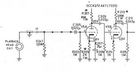
It would be great if you run your sims with only the first and second stage and see if your values match mine. See the attachment for what I have build so far.
Measurements are done with a Hitachi V-1585 scope which is a decent scope and double checked with a VTVM for AC as well as DMM for DC and AC. All show consistent measurements with each other.
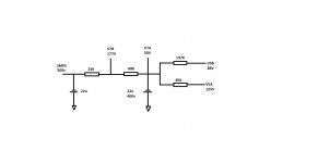
The power supply is a SMPS power supply outputting 300V (315V) @ 0.6mA and 6.3v at 4.5A. I know it's not the best solution but that's what I use for testing. I've successfully used this in other tube projects in the past.
Attached is the power schematic beyond the SMPS.
Measurements are done with a Hitachi V-1585 scope which is a decent scope and double checked with a VTVM for AC as well as DMM for DC and AC. All show consistent measurements with each other.
The power supply is a SMPS power supply outputting 300V (315V) @ 0.6mA and 6.3v at 4.5A. I know it's not the best solution but that's what I use for testing. I've successfully used this in other tube projects in the past.
Attached is the power schematic beyond the SMPS.
Attachments
Ok, here it is. I was not sure how to handle your power supply as it is not clear what you have when only stage V5 is powered. I adjusted RPS to get about 150V for the V5 tube supply. I also changed R207 and R213 to the values you indicated on your power supply sketch. There is only a 0.3 dB change in V5AP signal when disconnecting V5B stage by disconnecting between C209 and V5AP. I did not include that result. Are you adjusting your net equivalent of RPS when changing the number of stages you have built changes??
I did not include the influence the impact of scope loading, but that should be minimal with a 10meg or even a 1M probe setup.
How about a photo of your lashup.


I did not include the influence the impact of scope loading, but that should be minimal with a 10meg or even a 1M probe setup.
How about a photo of your lashup.
If you install LTSPICE (freeware) I can get you started with one of these simulation files (file type extension is .asc). It's really easy even if you have never run a simulation before!

I have LTSPICE installed and also loaded the tubes but didn't get farther than that. Could you provide the .asc file so I can load it?
Here it is, Toughest part is pointing to your model files with the .INC statement.
Mine is placed in "Documents\LTspiceXVII\lib\sub\Tube". If you place the models there it should find them.
Got an error message when attaching the 12ax7.inc file, hope it still works.
Mine is placed in "Documents\LTspiceXVII\lib\sub\Tube". If you place the models there it should find them.
Got an error message when attaching the 12ax7.inc file, hope it still works.
Attachments
- Home
- Amplifiers
- Tubes / Valves
- TapeHead Tube Preamp Schematic Question