Hi Guys,
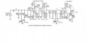
I've recently build a reel to reel playback tape head tube preamp. I have followed the Tandberg 64x tube preamp schematic however something is not adding up and maybe someone can clarify if this is normal behavior. I have checked the build and everything is as per schematic.
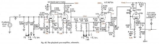
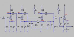
Tandberg doc specifies that the cathode follower output is 1.5V. Mine is 12.2mV which is a huge difference. I have traced the signal and the values can be seen in the attached schematics. Also, the plate and cathode voltages are correct in my build as specified in the Tandberg doc. I also removed the entire EQ part and the results are the same.
Did I do something wrong or the values measured look right to you?
Thanks
I've recently build a reel to reel playback tape head tube preamp. I have followed the Tandberg 64x tube preamp schematic however something is not adding up and maybe someone can clarify if this is normal behavior. I have checked the build and everything is as per schematic.
Tandberg doc specifies that the cathode follower output is 1.5V. Mine is 12.2mV which is a huge difference. I have traced the signal and the values can be seen in the attached schematics. Also, the plate and cathode voltages are correct in my build as specified in the Tandberg doc. I also removed the entire EQ part and the results are the same.
Did I do something wrong or the values measured look right to you?
Thanks
Attachments
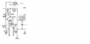
The 1.5 volts likely applies to the AC signal output level. As the follower is AC coupled via c225 I would expect near 0 dc voltage. On the other hand, the 1.11 volts on the grid of V7A should also be near zero. That could be a gassy tube or a leaky c211 or an open r215. Might also be a poor solder joint or a leakage path on the V7 socket, make sure connections are secure and clean.
Sorry, i should have clarified it. The values in red are signal values in AC. The values in black in the original schematic on the plate and cathode are DC and they match the measurements in my build. All components are brand new just ordered from digikey.
I’ve aslo tried 2 diferent 12au7 tubes, both NOS, with the same result. It seems that the signal entering at grid of first triode of 12au7 is at 1.11V AC. I was expecting the last stage and the cathode follower stage to amplify the voltage from 1.11V to roughly 1.5V ac but it looks like it does exactly the oposite bring it down to almost the same level as the input signal.
Does that make sense or is there something wrong?
Mandu, based on the oscilloscope reading, the amplitude of the signal is the same before and after c217. The signal comes neutered right out of the plate. Coming in at the grid at 1.1V and coming out at 16mV.
Disconnect the capacitor and measure the output directly at the plate. If still low, the cathode resistor could be open to ground.
Regards.
Regards.
I suspect you may have some incorrect capacitor values. The one with just numbers beside them are most like picoFarads like C215 and C219. Can you post a schematic with the actual values you have used?
Cheers
Ian
Cheers
Ian
I put this together in ltspice yesterday. The bias points were not in agreement with dromichet's schematic as you also surmised. Regardless there was still a lot of signal gain. Your suggestions look good. I was thinking my tube models were running hot, or that the original schematic had assumed near end of life tubes??
What is the cathode voltage you are measuring?
Can you Bypass the suspected tube cathode to ground with a 10 uF capacitor and see if there is increase in the output signal.
Otherwise can't troubleshoot properly
Regards.
Can you Bypass the suspected tube cathode to ground with a 10 uF capacitor and see if there is increase in the output signal.
Otherwise can't troubleshoot properly
Regards.
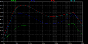
Rebiased schematic simulation. R229, R239, and R241 were changed to get closer bias point on V7A and V7B. AC response shows rather minor differences. Looks like the circuit is tolerant to large bias shifts. The only problematic bias in the original is V7A. Basically if you get any reasonable bias point on the tubes you should see AC performance similar to what I have shown. The issues with biasing might be due to the tube models for the sym not being ECC82S and ECC83S ??
Short story, if biasing is reasonable, the issue you are having can be isolated to AC only signal paths. Start with measuring all your bias points and report back.


Short story, if biasing is reasonable, the issue you are having can be isolated to AC only signal paths. Start with measuring all your bias points and report back.
Tip. Do not try to measure bias by probing the grids. It will not work. Probe cathodes instead.
Cheers
Ian
Cheers
Ian
Thank you very much for all your input. I've added my measurements by borrowing PotentiallyIncorrect's spice schematic, the original without any R value modifications.
Let me know if you need any other measurements. It looks like based on my measurements the signal output should be matching the spice simulation..... but it doesn't somehow.
I have used several new tubes as well as some older ones and all have very similar results.
Let me know if you need any other measurements. It looks like based on my measurements the signal output should be matching the spice simulation..... but it doesn't somehow.
I have used several new tubes as well as some older ones and all have very similar results.
Attachments
Wow, the models I have for these tubes must be way off. Another thread I will have to chase for another day! Your bias measurements are spot on with the schematic you provided, so the bias should produce results close to my sims.
If any of these resistors are low value or shorted, could be your problem. R209, 215, 235.
Possible open or low value caps. C207, 209, 211, 227, well frankly all caps.
Also, make sure wiring is actually true to the schematic. Something is way off to see signal gain as low as you report.
What frequency and input level are you using for the debug?
Possible open or low value caps. C207, 209, 211, 227, well frankly all caps.
Also, make sure wiring is actually true to the schematic. Something is way off to see signal gain as low as you report.
What frequency and input level are you using for the debug?
Last edited:
I've just checked the build for the second time and it looks true to the schematic. Also checked the values of the resistors you mentioned and they're ok. All caps are brand new as well so they should be ok.
I'm using a 400Hz signal at 5-6mV to simulate what come out of a tape head.
So far I've only built one channel. My next step is to build the second channel but stopping and measuring after each stage. Since my first stage doesn't seem to provide enough amplification it should be quite obvious right from the beginning.
Is measuring after each stage a valid test or do I need to build the entire circuit in order to get the right measurements? I'm thinking with a 5mV input the first stage should provide at least 150mV as your sim measured.
- Home
- Amplifiers
- Tubes / Valves
- TapeHead Tube Preamp Schematic Question