There are different generations of these axial caps: some feel very light when you weight them by hand. They look almost like empty shells. They dry out very quickly, even when unused. Others seem to last forever, and feel like they have a normal density.Pristine 🙂 Well when I went to school a long time ago teachers (some ex-Philips guys among them) wanted us to measure these (various series but all axial with the transparent blue sleeve) and axial ITT Marcon caps. After we measured these caps they mentioned the electrolyte in the blue axial caps to be Ranja 😀 They measured awful indeed. They were offered often in bulk at various electronic dump shops for many years and fellow DIYers warned each other for these. Philips later made excellent caps with solid aluminium, I still have large numbers in stock of these and regularly use these (128 SAL-RPM).
Ranja is a sugar sirup to make lemonade.
I can measure the ones I have kept (only the good ones, not those that are lemonade-based)
Yeah it is really too long ago to remember the series names but it were a few. Maybe I should look it up in my old school documents 🙂
Standard ITT Marcon then were a lot better. Never ran into a bad old one of those either contrary to the blue sleeve caps as used in 80s CD players.
Standard ITT Marcon then were a lot better. Never ran into a bad old one of those either contrary to the blue sleeve caps as used in 80s CD players.
I also have a good stock of historic ITT 10µ/25V axials, equivalent to the Philips I used in the amplifier, and contemporary. I can measure them too for comparison purposes.
Yes, now corrected.The 22K is now connected where it should.
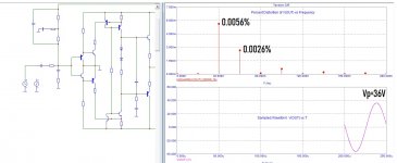
from what is written further in your post, I see that in the simulation they changed the circuit, reduced the resistance at the input and removed the dividers in the collector circuits.In the sim below, you see the voltage at point A (same as output in fact) together with the input voltage times 100K, with an offset removed to remain in the picture. The pp voltage in A is 70V, and the input voltage 12.8Vpp, a ratio of 5.4, meaning the OL gain is 540,000.
That's a sim, in reality the gain is more like ~450,000.
At the same time, it remains unclear what you still think and, most importantly, how it helps to improve the quality.
Mathematics is an exact science,
Is there a formula by which you calculate the voltage gain in a circuit this way?
Actually, I don't need it - you need it if you really want to improve your circuit, if not, sorry, I won't waste time...
I have added the resistors in the collectors mainly for dissipation and safety reasons: their influence on the overall gain is minor:
You can see it in this sim:

There is a formula for the gain, but it is extremely loose, like any open-loop gain computation for opamps for example. It is totally dependent on the Hoe of Q1 and Q3, which is linked to their Early voltage, but this value is highly variable and inaccurate.
Modern transistors tend to have a higher Vaf than what is stated in their models; in addition, Vaf is a crude approximation and depends on many secondary conditions.
You could compute a theoretical gain based on Vaf=100V, like in many models, but it would be wrong all the time, depending on the actual conditions and voltage excursion.
In addition, the load at point A is not actually a load: due to the negative impedance of the Tandem, it provides additional gain compared to the open circuit situation.
This increases (marginally) the gain at high frequencies for a MOS, and at all frequencies if M3 becomes a BJT.
Nothing of that matters very much: the gain can be 540,000 or 270,000, the end result will not vary very much: that's the strength and beauty of systems subjected to high levels of NFB
Btw, it could be very helpful if you could disclose your trick to reduce the THD of this VAS by a factor >1000: I eagerly await for it (and I am certainly not alone!)
You can see it in this sim:
There is a formula for the gain, but it is extremely loose, like any open-loop gain computation for opamps for example. It is totally dependent on the Hoe of Q1 and Q3, which is linked to their Early voltage, but this value is highly variable and inaccurate.
Modern transistors tend to have a higher Vaf than what is stated in their models; in addition, Vaf is a crude approximation and depends on many secondary conditions.
You could compute a theoretical gain based on Vaf=100V, like in many models, but it would be wrong all the time, depending on the actual conditions and voltage excursion.
In addition, the load at point A is not actually a load: due to the negative impedance of the Tandem, it provides additional gain compared to the open circuit situation.
This increases (marginally) the gain at high frequencies for a MOS, and at all frequencies if M3 becomes a BJT.
Nothing of that matters very much: the gain can be 540,000 or 270,000, the end result will not vary very much: that's the strength and beauty of systems subjected to high levels of NFB
Btw, it could be very helpful if you could disclose your trick to reduce the THD of this VAS by a factor >1000: I eagerly await for it (and I am certainly not alone!)

I have added the resistors in the collectors mainly for dissipation and safety reasons: their influence on the overall gain is minor:
Is a ratio of 180 times insignificant for you? curious.
here is a formula for the gain, but it is extremely loose, like any open-loop gain computation for opamps for example. It is totally dependent on the Hoe of Q1 and Q3, which is linked to their Early voltage, but this value is highly variable and inaccurate.
it's strange why I can accurately calculate the gain depending on the frequency up to the 3rd decimal place, and why is it not accurate for you ...
This is of great importance, because you have large distortion due to the low depth of the NFB depending on the frequency. However, you have some half a million ...Nothing of that matters very much: the gain can be 540,000 or 270,000, the end result will not vary very much: that's the strength and beauty of systems subjected to high levels of NFB
This is not a trick, you have large distortions due to insufficient gain with increasing frequency, and you don’t even try to limit the spectrum for this reason, of course there will be overload and large distortions ... Until you understand exactly how to correctly calculate the voltage gain depending on frequencies, tricks will not help you in any way.Btw, it could be very helpful if you could disclose your trick to reduce the THD of this VAS by a factor >1000: I eagerly await for it (and I am certainly not alone!)
This thread is fascinating. Hennady, could you please enlighten the less expert (trying to learn, like me) how to calculate this.how to correctly calculate the voltage gain depending on frequencies
References or textbooks are also welcome. Thanks.
Where did you find 180? It is 15.48/12.83 = 1.206Is a ratio of 180 times insignificant for you? curious.
Please enlighten us: I am always ready to learn from true experts.it's strange why I can accurately calculate the gain depending on the frequency up to the 3rd decimal place, and why is it not accurate for you ..
There are two parts in the calculation: one is easy and relatively accurate, it is the transconductance of the input transistors.
The second part is much trickier: it is the calculation of the output impedance of the current sources. It is doable but tedious for small-signal conditions, but it will be inaccurate because h22 or Vaf are rarely specified in datasheets, they can vary a lot, and anyway the circuit doesn't operate under small-signal conditions: the transistors see the full output swing, >70Vpp
I beg you not to shirk, you are an expert in the account of millions, earlier I asked you to show how you count 100 thousand here and there. And what about the gain at a frequency of 20 kHz? enlighten me, don't be afraid to be a guru...Please enlighten us: I am always ready to learn from true experts.
This thread is fascinating
I'm shocked myself )))
could you please enlighten the less expert (trying to learn, like me) how to calculate this.
References or textbooks are also welcome. Thanks.
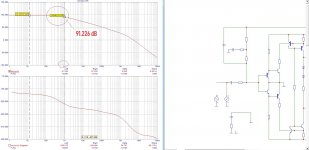
Сould you tell me what the voltage gain is in times at the value of this gain of 91.226 dB at a frequency of 1 kHz?
Including references to literature and formulas. I want to learn how to count in millions too.
Thanks
Attachments
Voltage gain (dB) = 20×log (Audio output voltage / Audio input voltage)
Is that correct ? But why in Times?
Is that correct ? But why in Times?
what do you think?Voltage gain (dB) = 20×log (Audio output voltage / Audio input voltage)
Is that correct ?
But why in Times?
is this a question for me? ask the author of the topic why times ....
I just asked you to translate dB into times - is it difficult for you?
10^(91.226/20) = 36416.65I just asked you to translate dB into times - is it difficult for you?
In Arial though 😉
Jean-Paul, I made a quick test here: https://www.diyaudio.com/community/...itors-tested-and-compared.390341/post-7124278Elvee did you ever measure those axial Philips capacitors?
I started a new thread to avoid cluttering this one with irrelevant material.
If you want more specifics tests, I might have the samples in my stash, you just have to ask
Oh you did not need to do that. I would have thrown all these away as I do with all electrolytic caps over 10 years old. No worries.
Thanks anyway, the results are more or less as expected. The ITT has lowest ESR.
Including a recent good quality 10 µF cap like a Panasonic FC/FM would have been nice. Probably will outperform all the others.
Thanks anyway, the results are more or less as expected. The ITT has lowest ESR.
Including a recent good quality 10 µF cap like a Panasonic FC/FM would have been nice. Probably will outperform all the others.
Last edited:
An important point worth noting about the Tandem topology: each output device has a completely different role/function, meaning they are not required to be complementary, identical or even similar.
In fact, using dissimilar devices might bring benefits: the Tandem error-correction principle works extremely well with BJT's (remember: 0.004% linearity), but not so well with MOSFETs (0.25% at best).
One could combine a BJT Tandem engine with a slave MOS for companion. The power BJT could in fact be a CFP BJT+MOS hybrid, to retain the bipolar nature, but with the advantages and robustness of a MOS (fitted with a Vth-eraser, of course).
The only requirements for the output devices are the power handling capability, voltage, current and SOA.
I have used identical transistors in my build, but that was just for convenience, it is certainly not a necessity
- Home
- Amplifiers
- Solid State
- TandyMOS is not your typical amplifier: