
I have tried the cross-coupling, but it always makes matters worse, for any combination of values.
Something that works, in combination with the RC network, is a resistor from the base to Vcc, to prebias the darlington to the threshold of conduction. Not elegant, and requiring a good accuracy to work well.
The ideal would be a completely non-switching solution for both transistors: presently, only the lower one conducts all the time.
Without the RC, the circuit is tantalizing close to a correct operation: oscillations only begin to break out when the positive excursion comes close to the maximum: with a proper 2 or 4 layers PCB, and a careful layout, it might be stable.
Perfboard is not ideal for high performance circuits
I modified the input/vas stage, and tried make it work with higher rails.
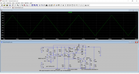
Actual results for sinus 1kHz look good.
But it's almost impossible to make square waves simulate well.
2nd schematic proposed by Steve in post #14 was handling square waves ok.
I know this is all premature, but I was just curious...

Actual results for sinus 1kHz look good.
But it's almost impossible to make square waves simulate well.
2nd schematic proposed by Steve in post #14 was handling square waves ok.
I know this is all premature, but I was just curious...
Attachments
This is version uses two NPN power transistors. It uses a Darlington slave to get enough current for 4 Ohms. But that causes stability issues so C1 around the op-amp provides a "pole splitting" that improves stability. Increasing the feedback resistors allows C1 to be quite small. The current mirror is done a bit differently to avoid the power diode in the output.
Attachments
I have (painstakingly) managed to stabilize the darlington version up to the clipping limit (after that, all hell breaks lose) without the initial RC compensation. It means adding a RC network in parallel with the 100 ohm BE, but it is very touchy and needs to be fine-tuned.
There is probably a problem with the ferrite bead: oscillations occur when the voltage is close to the maximum (positive), and the current probably exceeds the saturation limit; theoretically at least.
I will confirm this with a measurement. If the bead loses its properties at high currents, it will impair its suppressing action.
The largest ferrite bead I tested (~4µH) saturates at a few hundreds of mA.
This is the current vs. time plot for a fixed voltage step (2A/division). The waveform isn't clean, because it is the limit of my test bench, but it is obvious that it is not linear: it should be a regular sawtooth, but it quickly rises at a much steeper rate.
During the test, the bead heats up like hell, despite the low duty-cycle of the test.

Unfortunately, the saturation occurs at a time when the bead is most needed: at high currents, when the transconductance of the darlington is highest. For some reason the oscillation breaks out on the falling edge of the triangle, when the inductor releases its stored energy:

The darlington I used is integrated, and I left the 100R BE where it was. It is certainly suboptimal: a darlington constructed from discretes should have the lowest resistor across the final device, not the input.
It is probably possible, with some efforts, to make the topology reasonably stable without punishing compensations, but the clipping behaviour would have to be addressed, because it is currently awful.
Replacing the ferrite bead with a regular coil, capable of handling the peak current does not work, because the losses are too small. Damping should be added, but in a distributed manner, like in a bead: a brute parallel resistor does not work wel
This is the current vs. time plot for a fixed voltage step (2A/division). The waveform isn't clean, because it is the limit of my test bench, but it is obvious that it is not linear: it should be a regular sawtooth, but it quickly rises at a much steeper rate.
During the test, the bead heats up like hell, despite the low duty-cycle of the test.
Unfortunately, the saturation occurs at a time when the bead is most needed: at high currents, when the transconductance of the darlington is highest. For some reason the oscillation breaks out on the falling edge of the triangle, when the inductor releases its stored energy:
The darlington I used is integrated, and I left the 100R BE where it was. It is certainly suboptimal: a darlington constructed from discretes should have the lowest resistor across the final device, not the input.
It is probably possible, with some efforts, to make the topology reasonably stable without punishing compensations, but the clipping behaviour would have to be addressed, because it is currently awful.
Replacing the ferrite bead with a regular coil, capable of handling the peak current does not work, because the losses are too small. Damping should be added, but in a distributed manner, like in a bead: a brute parallel resistor does not work wel
I have tested Steve's idea of duplicating the feedback transistors on the darlington-equipped prototype, and it did wonders: the circuit is now calm and docile, without any additional compensation.
The ferrite bead is still required, but it can be smaller: ~1µH.
The circuit remains stable up to the clipping limit. The negative clipping is clean, but the recovery of the positive clipping is ugly. It can probably be fixed with a clamp or some other measures.
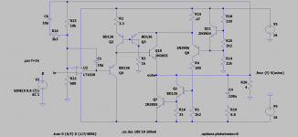
This is the circuit as I tested it:

I made a number of adaptations: R18 is 22 ohm, because there is no need for a large drive current, and R17 reduces the dissipation of Q4, without modifying the circuit's operation. In my protoptype, this was very necessary because I didn't thermally couple D1 and Q4, and after a few tens of seconds of power testing, the temperature delta caused the apparition of crossover distortion.
I didn't make other adaptations, but for a final project, all the values should be reviewed to take into account the darlington (which had been dropped-in with practically no modification) and the transistor duplication.
If an amplifier is redesigned from scratch to include all of these criteria, it will probably be easy and well-behaved
The ferrite bead is still required, but it can be smaller: ~1µH.
The circuit remains stable up to the clipping limit. The negative clipping is clean, but the recovery of the positive clipping is ugly. It can probably be fixed with a clamp or some other measures.
This is the circuit as I tested it:
I made a number of adaptations: R18 is 22 ohm, because there is no need for a large drive current, and R17 reduces the dissipation of Q4, without modifying the circuit's operation. In my protoptype, this was very necessary because I didn't thermally couple D1 and Q4, and after a few tens of seconds of power testing, the temperature delta caused the apparition of crossover distortion.
I didn't make other adaptations, but for a final project, all the values should be reviewed to take into account the darlington (which had been dropped-in with practically no modification) and the transistor duplication.
If an amplifier is redesigned from scratch to include all of these criteria, it will probably be easy and well-behaved
I have tested the above circuit with a 10kHz squarewave, and it was utterly catastrophic: a complete disaster.
This made me look into the fine details, and I discovered that the forward recovery of D1 was even more damaging than supposed. I had added C1 to compensate for the ~inductive behaviour of the diode, but it did damages of its own.
Fast diodes are specified mostly in terms of reverse recovery, because that's what matters in SMPS circuits, and forward recovery is often unspecified/neglected, because it matters for 2 or 3µs at most and causes <100mV overshoot, resulting in negligible losses. In addition, most modern diodes, including slow ones have a decent forward recovery behaviour, but some, including fast diodes are not that good.
The BYV71 is such an example. It caused a number of stability problems, and the C4 fix added some of its own.
In the end, I replaced D1 with a BYV27-50: an ultra-fast diode having a low reverse voltage rating, to focus on the forward properties.
This was a sea change: the behaviour changed completely, but an overshoot problem appeared: the R6/C4 network solved it neatly.
In the end I could safely dispense with the ferrite bead, the compensation network, and the positive clipping behaviour was greatly improved: not squeaky clean, but perfectly acceptable. I'll post pictures tomorrow.
I didn't adapt the fine-tuning components so far, but the preliminary results look extremely promising. In addition, the ADN of the circuit stems from a voltage-regulator, meaning it is unconditionally stable with any capacitive load, without any Zobel: I tested it with a 10µ PP capacitor and a 500µ bipolar cap as a pure load, and it behaved perfectly well, except that with a 100Hz squarewave the lab supply yielded with the 500µ, but with a triangle it remained perfect.
With 10µ, there was no ringing or overshoot. Completely insane by normal standards...
Here is the 10kHz triangle response, just below the clipping limit:

Now, the same but clipping:

A non-clipped squarewave, also 10kHz:

And this is the updated prototype, with the new BYV27 mounted in close proximity of the BD135:

Now, the same but clipping:
A non-clipped squarewave, also 10kHz:
And this is the updated prototype, with the new BYV27 mounted in close proximity of the BD135:
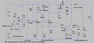
I have now adjusted the values of the linearity-correction resistors, R11 and R12:

With these tweaks, the THD is now 0.004%.... open-loop
With these tweaks, the THD is now 0.004%.... open-loop

This is a stab at the diamond buffer idea using this idea. With no op-amp feedback the THD is not bad but is sensitive to device matching. I thought I would have to do more to stabilize the bias, but it seems to work fine.
Attachments
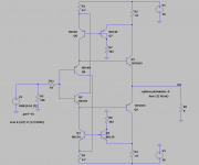
Interesting: it is the holy grail of the concept, but in practice the problem of two ~perfect half-buffers fighting against one another cannot be possible without some arbitration. Your cross-coupling is a good step towards solving the problem, but as you noticed, there are issues like matching. I tried something comparable a long time ago (I probably still have a prototype somewhere), and the results were interesting.
For some reason, it didn't qualify as worth pursuing. Maybe I was not tenacious enough. I'll try to dig out the prototype, if it still exists, and the documentation.
It was a long time ago, but I am sure I made it work: I remember I managed to blow up a big PETP metallized cap just to test its abilities at driving insane loads. It ended up in the rejects though, maybe for the wrong reasons.
Symmetry is desirable, because it cancels even harmonics, and because no side ever switches off. In the tandem, only one side is always on, and it is a weakness
I managed to retrieve both the prototype, and two versions of the documentations, a small miracle considering they date back from 20 or 25 years.
The first version of the schematic is practically identical to Steve's proposition, except for minor differences in components values. The upgraded version, corresponding to the prototype has a more elaborate arbitration scheme, and the cross-coupling has been removed.
I have no idea why I adopted these mods, or why I finally shelved the whole.
I am going to try to fire the proto up, to see if it still works and has issues (probably)
Amazing you keep all this stuff after so many years. I usually throw away all the junk when I move - every 6 years on average...
I have been living in the same place for ~25 years. Before that, I was very mobile and I changed location every 1~2 years. Very little remains from that earlier time....
I have tested the old proto: it still works, quite well in fact but it does not behave like an ideal spice building block. It is way above a "normal" diamond buffer, but it cannot compete with the tandem buffer: for example, the output impedance is not in the milliohm range. A good, stable circuit but not extraterrestrial.
In addition, it is not non-switching: each side turns off when inactive. The tandem is half-non-switching, which is not perfect, but a step in the right direction.
The prototype has some undocumented mods, probably to try to make it non-switching or at least workable, but the mods are minor and do not fundamentally alter the behaviour.
- Home
- Amplifiers
- Solid State
- Tandem-based amplifiers