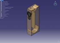
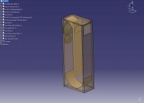
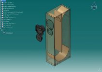
I put this model together this weekend for a TL based on an AC-180F1D and a Focal TI-121. I already own the drivers from other projects. The AC driver is a dual voice coil and the fs is about 37hz. I thought I would try something I read about years ago written by one of the Focal engineers in Speaker Builder (I forget which issue) where a DV driver is utilized in a 2-way driver set-up, however, one of the voice coils is connected to the band pass section of a 3-way crossover and utilized as a midrange. This has always sparked my interest so it thought I would take a swing at it for fun. If I can’t make it work I can always wire it in a 2-way configuration. If any of you have experience with this, or the box design for that matter, feel free to chime in. The TL itself I designed based on material I have researched from M. King and also calculators from various web sights and software modeling. The cab is 40 inches tall, 8 inches wide and 15 inches deep (exterior dim). The line length is about 67 inches and is a constant cross section area close to driver cone area
Attachments
Yes, I'm also curious. Is that a simulation program with CAD capability? It looks great. The only program I was aware of designed for TL modeling is the one by George Augspurger.
There was indeed a speaker where they used one coil normally, and another coil with a different crossover, in order to do some unusual shaping of the crossover response. I've also seen some designs where the second coil is crossed over at low frequencies, to create a kind of low frequency boost/baffle compensation.
But it's cool you're doing a TL. Consider a clear plex side, that can look really unique.
The only program I was aware of designed for TL modeling is the one by George Augspurger.
In Fall 1999 when Augspurger's and Martin King's modeling software were pretty much neck & neck, But with 10 years on continuous development of the latter, and none for the former, MJK is way ahead... for a Straight TL like this, his free alignment tables would do the job.
dave
This double VC drivers setup was indeed very fashionable in France 30 years ago.
One coil was with a low pass, say 2500 Hz, to meet the tweeter, the other coil was with a low pass around 100 Hz.
The idea was to reinforce the low range. Only first order filters could be used.
Dunno, but phase shift could be an issue of this design.
BTW, I like your graphics.
One coil was with a low pass, say 2500 Hz, to meet the tweeter, the other coil was with a low pass around 100 Hz.
The idea was to reinforce the low range. Only first order filters could be used.
Dunno, but phase shift could be an issue of this design.
BTW, I like your graphics.
I model in Catia. I have been a mechanical design engineer for many years. The audio portion of the design process takes place separate from the CAD modeling. Catia and SolidWorks are a huge help when doing complex loudspeaker box design. You can overcome many fit and finish issues before you ever cut material and also correct miscalculations in the fundamental design itself. For instance, when I did the first hand sketch based on the audio software calcs with dimensions, the line length hand calc was 67 inches. Once I modeled the box in Catia based on those calcs, the “Effective” line length was actually 83 inches. So, I made the correction and the box goy much smaller. The box looked much more in proportion to what others had done based on the MJK data as well.
I am very excited that you all like this idea. I have been building very complex line array and exotic system design for so long that I have forgotten why I started hi fi DIY in the first place. Right now I am running a tri-amp stereo system with 5 amps and 2 electronic crossovers. It will be so fun to just set a purist system with a tube amp and pre amp of about 25 watts and 2 speakers and dial some passive crossovers to get it right. I will really enjoy the twist of the 3-way crossover.
MLC
There was indeed a speaker where they used one coil normally, and another coil with a different crossover, in order to do some unusual shaping of the crossover response. I've also seen some designs where the second coil is crossed over at low frequencies, to create a kind of low frequency boost/baffle compensation.
I measured some in-walls that did the bass level via dual vc and switches. It seemed to work pretty well. Was it Speakercraft?
Not sure what midrange crossover will do and a 2 1/2 way approach doesn't help since it's dual VC rather than dual source. Still, might be some interesting curve shaping possible.
David S.
For the last couple of evenings I have been sorting through the MJK derivations trying to solve an issue with this particular DVC driver. For some reason, when I do the hand calcs for a TL utilizing the AC-180F1D, the enclosure gets unusually large in both cross sectional area and line length. So far, it looks like I have isolated it to the driver BL factor but more analysis is needed on my part. The BL on this driver is listed @ 3.3 (no units given) which seems low (about 1/3) relative to other drivers I have modeled. I have not measured the driver. I will do this right after Christmas when I have them broken in. There is also the possibility of a mathematical error on my part, however, when I run other drivers parameters with hand calcs everything seems reasonable.
- Status
- Not open for further replies.
- Home
- Loudspeakers
- Multi-Way
- Taking a swing @ TL