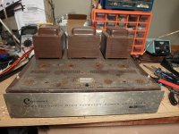
This thread will chronicle the rebuild of a 1961 Harman Kardon Citation V I picked up cheap on eBay a few years ago. There's not a lot of quality documentation available on the internet for this amplifier, so part of the intention here is to help fill that gap for future rebuilders. Your feedback and participation is of course essential.
Speaking of poor documentation, if anyone has a decent copy of the *complete* original assembly documentation for a Citation V, I'd like to chat with you. There's only one copy floating around the web and it's missing all the assembly diagrams and pictorials, which makes it tedious to identify and trace all the parts. There's also a Sams Photofacts guide floating around but it looks like a low rez scan of a fax of a photocopy, all done with 1970's equipment, the pictures are pretty difficult to read. And there is an error in the Sams schematic which doesn't inspire (in me at least) much confidence in the rest of the information.
Before anyone mentions it, yes I know about Jim McShane, and his offerings will likely be an important part of this rebuild as it progresses.
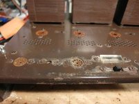
About this particular amp, its chassis is not in great condition, it has some rusted areas on the front of the deck that has damaged the silkscreened text in places, and the faceplate has a heartbreaking set of deep scratches across it that will be challenging to deal with. I'll be looking for ideas there. The guts have already undergone some (poorly executed) minor updates and/or repairs by the looks of it. The transformers all look like they are in great condition, thank heavens.
The plan is to completely strip the amp down to its essentials and refresh and renew as much as possible. I have photographed the guts from every possible angle, but I won't upload all those photos here unless there is some specific need to show something. I used to be a technical illustrator, and I like to draw using Adobe Illustrator almost as much as I enjoy working on tube amps, so expect plenty of drawings and diagrams where appropriate.
If this thread is of any interest, stay tuned...
..Todd (TAJ)
Speaking of poor documentation, if anyone has a decent copy of the *complete* original assembly documentation for a Citation V, I'd like to chat with you. There's only one copy floating around the web and it's missing all the assembly diagrams and pictorials, which makes it tedious to identify and trace all the parts. There's also a Sams Photofacts guide floating around but it looks like a low rez scan of a fax of a photocopy, all done with 1970's equipment, the pictures are pretty difficult to read. And there is an error in the Sams schematic which doesn't inspire (in me at least) much confidence in the rest of the information.
Before anyone mentions it, yes I know about Jim McShane, and his offerings will likely be an important part of this rebuild as it progresses.
About this particular amp, its chassis is not in great condition, it has some rusted areas on the front of the deck that has damaged the silkscreened text in places, and the faceplate has a heartbreaking set of deep scratches across it that will be challenging to deal with. I'll be looking for ideas there. The guts have already undergone some (poorly executed) minor updates and/or repairs by the looks of it. The transformers all look like they are in great condition, thank heavens.
The plan is to completely strip the amp down to its essentials and refresh and renew as much as possible. I have photographed the guts from every possible angle, but I won't upload all those photos here unless there is some specific need to show something. I used to be a technical illustrator, and I like to draw using Adobe Illustrator almost as much as I enjoy working on tube amps, so expect plenty of drawings and diagrams where appropriate.
If this thread is of any interest, stay tuned...
..Todd (TAJ)
Attachments
Step 1 was to photograph everything in detail. That's done, so next up is to strip *everything* off of the chassis so that it can be repaired and refinished if and where possible. I'm taking this part slowly, just to ensure I have things photographed or diagrammed properly before disassembling. I'm not sure how I'm going to tackle refinishing the chassis. I don't want to repaint it until I have a plan to re-apply all the lettering.
I've thought of a few approaches for the lettering;
Colour: One thing that bothers me about these Citation amps is the colour of the transformers. It's a subtle difference but it's not quite the same classier looking 'charcoal brown' as the chassis. It's slightly lighter and rustier; it looks more like a chocolate bar. I'd like to nail the chassis brown colour and match the transformers to that. I've even considered painting the transformers black, which would greatly appeal to me, but of course vintage purists would object to that.
..Todd
I've thought of a few approaches for the lettering;
- waterslide decals with a clearcoat on top. The downside to this is that the outline of the decal membrane tends to show unless you apply lots of clearcoat and sand between coats. This seems like the best approach though.
- DIY silkscreening. I've never done this and it looks like it would take a lot of messy practice attempts to nail the technique. I'm pretty sure I don't want to go that route.
- Some kind of printed dry transfer product with a clearcoat on top. Not really sure if there's any product suitable for this. Maybe. Anyone have any experience with that?
- Pro silkscreening. No budget for that. This is DIY after all.
Colour: One thing that bothers me about these Citation amps is the colour of the transformers. It's a subtle difference but it's not quite the same classier looking 'charcoal brown' as the chassis. It's slightly lighter and rustier; it looks more like a chocolate bar. I'd like to nail the chassis brown colour and match the transformers to that. I've even considered painting the transformers black, which would greatly appeal to me, but of course vintage purists would object to that.
..Todd
Attachments
Last edited:
Good luck with your project. I have a Citation V I rebuilt 25 years ago. I would like to rebuild it again with modern caps and a CCS in the tail of the LTP. I have the manual but am south for the winter and won't be home for another 8 weeks. I think you will have to completely strip your chassis and maybe powder coat it; those corrosion pits look bad.
Surprise (not), Jim McShane can tell you what automotive painting supplies to buy. 😉 Remember, Jim's "day job" is in the automotive industry.
If, as I think, you have rust on the lam stacks, buy a firm brand X toothbrush and gently knock loose rust off. Follow with a rust conversion conversion product, like Duro Xtend, and then paint. You, most definitely, do not want to remove any OEM lacquer or oxide from the laminations. JMO, black lam stacks would be OK with chocolate brown elsewhere.
If, as I think, you have rust on the lam stacks, buy a firm brand X toothbrush and gently knock loose rust off. Follow with a rust conversion conversion product, like Duro Xtend, and then paint. You, most definitely, do not want to remove any OEM lacquer or oxide from the laminations. JMO, black lam stacks would be OK with chocolate brown elsewhere.
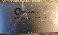
Here's a pic of the nasty faceplate scratches. I could certainly sand them out, but I'd loose all the silkscreened graphics. I have recreated all the graphics in vector format in case I need to re-apply them to a refinished faceplate somehow, but I don't really know how I'd do that. Waterslide decals again maybe.
Or maybe I can fill/hide the scratches somehow. Ideas welcome.
..Todd
Or maybe I can fill/hide the scratches somehow. Ideas welcome.
..Todd
Attachments

Last edited:
Thanks for the tips, Eli.
Palustris, yup, that corrosion is nasty. I have a friend in the powder coating business. I'll have a chat with him to see if he can assist. I'm considering adding a CCS as well. Keep in touch about that manual. I will not be rushing through this.
..Todd
Palustris, yup, that corrosion is nasty. I have a friend in the powder coating business. I'll have a chat with him to see if he can assist. I'm considering adding a CCS as well. Keep in touch about that manual. I will not be rushing through this.
..Todd
Last edited:

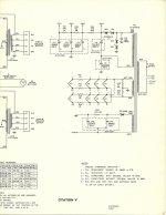
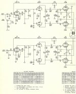
Here is a copy of the original schematic.
Thanks! Clear as a bell and no yellowing, what's not to like.

I have the original split into 2 scans, which I'm uploading, just in case.
Attachments
Eli, I thought I sent you that final copy. Someone on this forum pieced the two together from the separates I sent them. BTW, I also have the original construction manual complete with all the BIG pictorials. But they are way to big to copy.
Eli, I thought I sent you that final copy. Someone on this forum pieced the two together from the separates I sent them. BTW, I also have the original construction manual complete with all the BIG pictorials. But they are way to big to copy.
Get in touch with Jim McShane. Perhaps, with his automotive industry contacts, he knows somebody in our neck of the woods with the equipment needed to make good gifs of the big pictorials. Good gifs "blow up" very nicely in IrfanView.
HollowState, I have that same schematic (the whole original one). If you want to send me those manual and pictorials, I'll scan them properly on the big toys at work, and send them right back. PM me if you're game.
And of course I've drawn my own schematic at some point in the past (2011 apparently) as I am prone to do. I found it on a different forum but it probably came from here originally. I'll add it here for posterity(attached).
..Todd
And of course I've drawn my own schematic at some point in the past (2011 apparently) as I am prone to do. I found it on a different forum but it probably came from here originally. I'll add it here for posterity(attached).
..Todd
Attachments
I had a Citation V back in 1992 (god I'm getting old) - did a recap job, both electrolytics and couplers. The lack of bias control - something at the time I was too inexperienced to add - meant that the amplifier ran normal 6L6GCs right at the ragged edge. For example a black plate RCA would should red band right along the plate seam. This amp originally came with 7581s would could take the abuse.
At the time the Soviet-made 5881WXT could take the heat.
Objectively speaking, I found the amp rather dry. Coupled with a Thorens TD166 table and a Grado Black, an Adcom 565, and a pair of Snell J3s was not a lush, tubey affair compared to my previous amps - Dynaco Mark IVs. One of my least favorite stereos I've ever put together - but it was a highly reflective room.
"Objectively speaking, I found the amp rather dry. Coupled with a Thorens TD166 table and a Grado Black, an Adcom 565, and a pair of Snell J3s was not a lush, tubey affair compared to my previous amps - Dynaco Mark IVs. One of my least favorite stereos I've ever put together - but it was a highly reflective room."
Once again, the system synergy issue surfaces. Stu Hegeman voiced his amps honest, not euphonic. They are pretty darned neutral, but the very annoying artifacts so frequently encountered with SS are absent. You might have been happier with a different preamp. JMO, a little 2nd order HD is good.
Once again, the system synergy issue surfaces. Stu Hegeman voiced his amps honest, not euphonic. They are pretty darned neutral, but the very annoying artifacts so frequently encountered with SS are absent. You might have been happier with a different preamp. JMO, a little 2nd order HD is good.
Objectively speaking, I found the amp rather dry.
I subject to that statement.

...The lack of bias control - something at the time I was too inexperienced to add - meant that the amplifier ran normal 6L6GCs right at the ragged edge....
Adding a couple bias pots is a worthwhile mod I'll consider.
..Todd
Last edited:
I have a photocopy of the entire HK assembly manual incl. the large pictoral diagrams cut into 8x11 size chunks. Let me know if you need anything in particular but I don't have time to scan the whole thing. Its like 80 pages IIRC and my scanner doesn't have a doc feeder. The pictures you'll take are all you really need though.
I bought one on ebay around '98 and completely rebuilt it. Be careful with the meter and adjustment pots...unobtanium...although McShane has a reasonable replacement for the meter last I checked. I agree it runs the tubes right at the ragged edge. This was fine 15 years ago when you could still get a quad of NOS Philips ECG 7581A's for $100 or less but next time I spend any time with mine I'm going to back it off 20% or so while I have it open.
Its a nice amp and drove a set of magnepans I used to have pretty well. My ST70 couldn't quite cut it, I'm guessing because its PS isn't as tight. The V is a very neutral amp though. Sounds like good SS to me, which may or may not be your cup of tea.
If I were you I'd be very attempted to leave it as-is and just replace the caps and any drifted resistors. But I like rusty stuff like that. Its very hard to get a rebuild "correct" if that's what you are going for.
Last edited:
I have a photocopy of the entire HK assembly manual incl. blow-ups of the large pictoral diagrams. Let me know if you need anything in particular but I don't have time to scan the whole thing.
Thanks jdarg,
What would be very helpful at this point is a scan of the terminal board A pictorial. That would simplify the autopsy.
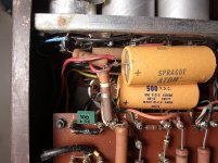
Today's update: I've found that the original 90+30+30uF multi-can cap (for the screen and upstream nodes) was replaced with a 60+40uF can paralleled together for the screen supply, and a pair of 20uF Sprague Atoms were bodged in for the upstream nodes. The date code on the replacement caps is 1966, so that was an old repair.
Sams photofacts uses different identifiers for C1 and C3. They are reversed from HK's schematic. Not sure yet if that's just an error, or if they went their own direction with many of those.
..Todd
Attachments
Last edited:
Well, here's an interesting bodge. These 5.6 ohm resistors are essentially connected between the 2 output tube cathodes with their center tap (light blue wire) connected to power ground, but only on 1 channel. It looks like this solution successfully released some of the smoke. 
I don't think I'll keep this mod. 🙄
..Todd
I don't think I'll keep this mod. 🙄
..Todd
Attachments

The Sams schematic uses different identifiers for everything. There are more differences in the schematics...
The HK schematic shows 1K resistors for R18/R19 between the output tube cathodes and bias control. The Sams schematic shows 15k and (10k). This amp has 10k resistors installed there.
(I'm not sure what those resistors are for...)
..Todd
The HK schematic shows 1K resistors for R18/R19 between the output tube cathodes and bias control. The Sams schematic shows 15k and (10k). This amp has 10k resistors installed there.
(I'm not sure what those resistors are for...)
..Todd
Attachments
The Sams schematic is known to be incorrect. Don't use it! Stick, exclusively, to what HollowState uploaded.
Right. Completely agree, Eli. I'm just chronicling everything I find and thinking out loud - so to speak.
So here's the question on my mind: why was this amp originally built with 10k resistors in this spot (and they do look original.). Its unlikely the kit builder followed the Sams docs initially or used parts other than the ones that came with the kit. It makes me wonder if there's another rev of the HK schematic floating around.
Can one of the resident engineers here say what these resistors are for? A local feedback loop? Sending some -vbias to the cathode for some reason? Or just a final tweak of the bias voltage?
..Todd
Last edited:
- Home
- Amplifiers
- Tubes / Valves
- TAJ's Harman Kardon Citation V rebuild thread