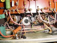
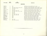
This resistor inconsistency got me to wondering. So I went to the attic and took a look at my HK Citation 5 which I inherited through the New Jersey Audio Society a few years back. Mine also has 10K ½W resistors as R18, 19, 40 & 41. They can be seen in the picture below. Further, the original parts list says they are 10K. Now I wonder if there is not a print error on the schematic.
Attachments
Last edited:
This resistor inconsistency got me to wondering. So I went to the attic and took a look at my HK Citation 5 which I inherited through the New Jersey Audio Society a few years back. Mine also has 10K ½W resistors as R18, 19, 40 & 41. They can be seen in the picture below. Further, the original parts list says they are 10K. Now I wonder if there is not a print error on the schematic.
Perhaps you should pass your findings on to Jim McShane. "Mr. Citation" may have input useful to all of this thread's posters.
Mine also has 10K ½W resistors as R18, 19, 40 & 41. They can be seen in the picture below. Further, the original parts list says they are 10K. Now I wonder if there is not a print error on the schematic.
HollowState,
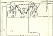
Does your original paper schematic match the scanned schematic you posted? (Assuming you have one.) A closer look at the scan (in post #18 above) shows it may have once said 10k as there is an obvious gap where a missing second digit probably lived. The other nearby 1k values don't have that additional space available.
Did the original docs include the schematic?
..Todd
Last edited:
Yes in both cases. And yes it does seem to have a space where a 0 could have, or should have, been. I have emailed Jim. And I am now thinking it is 10KΩ. The original schematic is an 11 by 17 fold out.HollowState,
Does your original paper schematic match the scanned schematic you posted?
Did the original docs include the schematic?
Last edited:
This was Jim's reply.
Hi Victor,
"I supply 1K carbon comp resistors in those positions. They work well, and since the power tubes are pentodes there is essentially zero Miller effect. so 1K it is."
"If you look close at the schematic it looks like there should be a zero in there after the 1 on two of them, but the other two show a “normal” 1K print."
"I will tell you there’s no harm in using 1K, but if 10K is what is used in the amp you have then don’t worry. It’s not an issue. It may have been an error or a running change."
Regards,
Jim McShane
McShane Design
Apparently either value works ok. What I do see happening is a reduction in negative bias voltage applied to the grids. This occurs because the ends of the centering pot are brought closer to ground with a 1K instead of 10K. So the outputs will run a little hotter. But it may not be enough to matter much.
This was Jim's reply.
Hi Victor,
"I supply 1K carbon comp resistors in those positions. They work well, and since the power tubes are pentodes there is essentially zero Miller effect. so 1K it is."
"If you look close at the schematic it looks like there should be a zero in there after the 1 on two of them, but the other two show a “normal” 1K print."
"I will tell you there’s no harm in using 1K, but if 10K is what is used in the amp you have then don’t worry. It’s not an issue. It may have been an error or a running change."
Regards,
Jim McShane
McShane Design
Apparently either value works ok. What I do see happening is a reduction in negative bias voltage applied to the grids. This occurs because the ends of the centering pot are brought closer to ground with a 1K instead of 10K. So the outputs will run a little hotter. But it may not be enough to matter much.
The 1K resistors are grid stoppers. One end of the 1K goes to the tube grid which has a VERY high resistance. You aren't likely to see any other than a very TINY change. The current through that resistor is maybe a few microamps.
You DO need to pay attention to the bias voltage though, since H-K ran the power tubes so close to their limits - or even over spec.
The resistors in question were not the grid stoppers. It is the ones from each end of the DC balance pot to the cathodes.
Oops, sorry if I missed that.
There were a lot of resistor value changes made in the Cit V, and I honestly can't tell any difference on any of them.
Humble apologies for my error...
There were a lot of resistor value changes made in the Cit V, and I honestly can't tell any difference on any of them.
Humble apologies for my error...
Let us assume the wiper on the pot (R15) is set in its center position. A quick calculation leads me to the following conclusions:
If R18 and R19 are 1k both output tubes will have approximately -15 V on their grids.
If R18 and R19 are 10k both output tubes will have approximately -43 V on their grids.
If R18 and R19 are 15k both output tubes will have approximately -46 V on their grids.
The correct value is definitely not 1k.
Torben
Last edited:
Let us assume the wiper on the pot (R15) is set in its center position. A quick calculation leads me to the following conclusions:
If R18 and R19 are 1k both output tubes will have approximately -15 V on their grids.
If R18 and R19 are 10k both output tubes will have approximately -43 V on their grids.
If R18 and R19 are 15k both output tubes will have approximately -46 V on their grids.
The correct value is definitely not 1k.
Torben
That's good information. Thanks Torben.
Just curious, what is the impedance the output transformer is presenting to the output tubes (assuming the appropriate speaker load is connected)?
..Todd
..Todd
Just curious, what is the impedance the output transformer is presenting to the output tubes (assuming the appropriate speaker load is connected)?
..Todd
The SAMS should list it if you have access to it. Otherwise you can do a simple test to determine it:
Take a loose output transformer and connect 120v (wall voltage) to the extreme ends of the primary. Take a meter reading of the voltage at the 16 ohm tap. Also take a voltage reading of the voltage going into the transformer. The more accurate the measurements, the better. These 2 voltages will give you the winding ratio (primary v / 16 ohm tap v)
So to figure out primary impedance, it's (turns ratio squared) X 16 = primary impedance.
Thanks. I'll check the Sams docs when I get home. Yes, I know how to measure it, but I wanted to ask first in case it's common knowledge.
..Todd
The OPTs are 4K P-P according to Sams. I will still probably measure these at some point.
..Todd
..Todd
This resistor inconsistency got me to wondering. So I went to the attic and took a look at my HK Citation 5 which I inherited through the New Jersey Audio Society a few years back. Mine also has 10K ½W resistors as R18, 19, 40 & 41. They can be seen in the picture below. Further, the original parts list says they are 10K. Now I wonder if there is not a print error on the schematic.
My Citation V manual has a typed addendum sheet that states:
CITATION V ADDENDUM SHEET
Before proceeding with the construction of your kit please make the following correction to your schematic diagram:
Change the value of the following resistors from 1,000 ohms to 10,000 ohms.
R18, R19, R40, R41
Looking at the factory diagram, there is more space between "1" and "K" on those parts than the other 1K resistors in the amp (like R8.) This suggests an inadvertently dropped "0" from the schematic vs. some sort of production change, but that's another possibility. Possibly differences in the meters. IIRC some also had 10R vs 3R3 cathode resistors - perhaps also related to a meter changeover.
I've also seen differences in some of the small pf caps on my citation v vs. others on the web. I think the Sams schematic reflects those alternates though.
Last edited:
Yes it is solved with 10K resistors as I suspected. But there is still a significant error on Sam's at the input 12BY7 tube screen capacitor for both channels.Mystery solved. Thanks jdarg.
..Todd
Yes it is solved with 10K resistors as I suspected. But there is still a significant error on Sam's at the input 12BY7 tube screen capacitor for both channels.
Yup, Jim's note about that is pretty prominent on the web when googling for Citation V info. I think Eli said it best:
"The Sams schematic is known to be incorrect. Don't use it! "
..Todd
Todd,The OPTs are 4K P-P according to Sams. I will still probably measure these at some point.
..Todd
Have you gotten around to measuring the actual impedance on the Cit V output transformers? (Or anyone else.)
I shall be grateful for this information.
- Home
- Amplifiers
- Tubes / Valves
- TAJ's Harman Kardon Citation V rebuild thread