Hi,
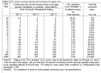
I wasn't really sure where to post this... This is a screenshot from the FAA Aircraft Standard Practices Manual "AC 43.13.1B". I haven't used this since college, and was wondering if these numbers look fairly accurate for the purposes of a power amps internal wiring. There are all sorts of charts online(google search), but most are in conflict with each other. Thanks to anyone who can help 🙂
- Tim
Attachments
I would be careful with this. It may be enough to keep aircraft flying with a 1 to 5 safety margin, but this is audio!
Jan
Jan
Thanks Jan, appreciate the response. Do you know if there is a similar table or plot that would be better suited for building amps?
Copper will pass 1000Amps per square inch. It equates roughly that 2.5mm T+E household cable will pass 25Amps, 1mm 10Amps 8mm 80Amps etc without much voltage drop.
The insulation is a different matter. PVC is most common. Some prefer Teflon or PTFE; each to their own. After all electrical current is electrical current regardless of how it is used.
The insulation is a different matter. PVC is most common. Some prefer Teflon or PTFE; each to their own. After all electrical current is electrical current regardless of how it is used.
Thanks JonSnell. I have access to PTFE, and Kapton insulated wires fairly easily(and cheap; through a previous employer). I've also recently found a sorce for TEW 600V 105c wire as well(although more expensive).
Working in Avionics has spoiled me. I haven't had to use a significant amount of my previously learned knowledge regarding electronics in the past 10 years. I've started into this world of DIY audio as a hobby, hoping to bring back some of the knowledge, and continue to grow it. So far I am learning more than I am remembering(I think!) LOL.
Working in Avionics has spoiled me. I haven't had to use a significant amount of my previously learned knowledge regarding electronics in the past 10 years. I've started into this world of DIY audio as a hobby, hoping to bring back some of the knowledge, and continue to grow it. So far I am learning more than I am remembering(I think!) LOL.
The old standard was 14 X 0076, that is 14 strands .0076 thou diameter was used for general cabinet and chassis wiring. Obviously current in heater supplies and large power amplifiers must be considered. I favour solid core 0.5mm for most static wiring. Easier to use than flexible multicore and looks neater. Obviously if more than 1/2 Amp I use 1.0mm. Always using flex to feed connectors, that allows for movement. I rewired the engine electrics of a 1967 MkII Jaguar with PTFE coated cable. I thought it would be good but if you make a sharp corner, in time the PTFE splits open, revealing the bare conductor. Fault finding wasn't fun!
There are MANY conditions attached to that very specific duty that you would be very unwise to adopt that table for any audio duty at home !Hi,
I wasn't really sure where to post this... This is a screenshot from the FAA Aircraft Standard Practices Manual "AC 43.13.1B". I haven't used this since college, and was wondering if these numbers look fairly accurate for the purposes of a power amps internal wiring. There are all sorts of charts online(google search), but most are in conflict with each other. Thanks to anyone who can help 🙂
- Tim
Transformers used to use 3.1A/sqmm, but this has crept up as copper prices went up. We see a few over-rated transformers using as much as 5A/sqmm.
Jon's example 14*0.0076" is roughly 0.4sqmm and would be good for upto 1.2Arms continuous and many amperes for transient duty.
0.6mm diameter hook up wire is 0.28sqmm and is good for upto 0.8A continuous. It's what I use (as twisted pairs) for most of my internal signal and power wiring.
There are a few duties where volts drop becomes a limiting condition. That may require a thicker cable than simply using maxium insulation temperature. You can calculate your Vdrop from the resistance taken from data tables and your installation length times your peak, or transient, or continuous current.
Last edited:
Appreciate the advice! I agree with you about the PTFE wiring. It is a common fault in "vibration aeras"on the aircraft I work on. I get my money's worth out of my multi-meter for sure!The old standard was 14 X 0076, that is 14 strands .0076 thou diameter was used for general cabinet and chassis wiring. Obviously current in heater supplies and large power amplifiers must be considered. I favour solid core 0.5mm for most static wiring. Easier to use than flexible multicore and looks neater. Obviously if more than 1/2 Amp I use 1.0mm. Always using flex to feed connectors, that allows for movement. I rewired the engine electrics of a 1967 MkII Jaguar with PTFE coated cable. I thought it would be good but if you make a sharp corner, in time the PTFE splits open, revealing the bare conductor. Fault finding wasn't fun!
There are MANY conditions attached to that very specific duty that you would be very unwise to adopt that table for any audio duty at home !
Transformers used to use 3.1A/sqmm, but this has crept up as copper prices went up. We see a few over-rated transformers using as much as 5A/sqmm.
Jon's example 14*0.0076" is roughly 0.4sqmm and would be good for upto 1.2Arms continuous and many amperes for transient duty.
0.6mm diameter hook up wire is 0.28sqmm and is good for upto 0.8A continuous. It's what I use (as twisted pairs) for most of my internal signal and power wiring.
After endless searching and many varying opinons, I ended up going through my old college notes(which appear to be not applicable to DIYA 🙂 ).
At the moment I am specifically interested in the PSU wiring for my Honey Badger. I have been trying to do the foot work/ proper research for a) safety, and b) so I can make educated decisions, but am having a hard time finding reliable information.
The build guide suggests at least 16 AWG for the PSU wiring, but most people I speak with suggest 10-12 AWG. I have a fair amount of 14AWG PTFE Three-wire twisted shielded wire, but am not confident/ educated enough to say its safe to use in this situation. PSUD2 shows a worst case 8.3A for my PSU, and the rail fuses are set to 4A.
I firmly believe it is better to teach a man to fish, than to give him the fish (as the old saying goes). That being said; It is a real pain sometimes with differing opinions 🙂
The operative word is 'continuous'.
To the US NEC that 'continuous' is 3 hours, steady state.
To audiophiles 'continuous' only applies to Class "A" power amplifiers.
To the US NEC that 'continuous' is 3 hours, steady state.
To audiophiles 'continuous' only applies to Class "A" power amplifiers.
The operative word is 'continuous'.
To the US NEC that 'continuous' is 3 hours, steady state.
To audiophiles 'continuous' only applies to Class "A" power amplifiers.
That's why I originally thought the numbers would be an OK guideline(error on the safe side). Compared the the link ( https://en.wikipedia.org/wiki/American_wire_gauge ) suggested by Tedknowlegy. The numbers are more restrictive in the aviation chart (although it is for a different type of insulation).
The aviation chart is for bundles of 32 cables. That's got to make a huge difference in de rating. On the other hand, don't think there's any downside to large power supply cables.
Transformers used to use 3.1A/sqmm.....
Jon's example 14*0.0076" is roughly 0.4sqmm and would be good for upto 1.2Arms continuous and many amperes for transient duty.
0.6mm diameter hook up wire is 0.28sqmm and is good for upto 0.8A continuous. It's what I use (as twisted pairs) for most of my internal signal and power wiring.
Using the ratio's suggseted above I came up with the following:
10AWG = 2.59mm = 5.26sqmm --> 16.3A
12AWG = 2.05mm = 3.3sqmm --> 10.23A
14AWG = 1.63mm = 2.1sqmm --> 6.51A
Do these seem like reasonable current limits for the gauges selected? (Keeping in mind that the longest wire will be approx 12-15 inches; I think)
Those are very reasonable where you know that the insulation does not overheat.
PVC does not like excessive heat so it needs to be fairly well cooled. A twisted pair leaves most of the surface area exposed to the cooling air.
Where you have an insulator that tolerates heat better and you have good cooling you can comfortably double those currents to 6A/sqmm.
It's the insulation that you need to take care of.
looking at your table you will see that the ~3A/sqmm is not far off their 105°C current values. Now look at note #1 and see they have allowed for Ta=70°C. That means their table allows for a 35C degree rise. That would be pretty cool in cable that is exposed to ambient air of 21°C.
BTW,
thin cables have more surface area than thick cables, so the 3A/sqmm or 6A/sqmm only holds true over a small range of sizes. Very thick cables will run hotter and may need to be de-rated. ultra thin cables will run cooler and can take more current. Flat thin traces have enormous surface area and can take enormous current densities.
And finally I'll repeat
There are a few duties where volts drop becomes a limiting condition.
Last edited:
Those are very reasonable where you know that the insulation does not overheat.
PVC does not like excessive heat so it needs to be fairly well cooled. A twisted pair leaves most of the surface area exposed to the cooling air.
Where you have an insulator that tolerates heat better and you have good cooling you can comfortably double those currents to 6A/sqmm.
It's the insulation that you need to take care of.
looking at your table you will see that the ~3A/sqmm is not far off their 105°C current values. Now look at note #1 and see they have allowed for Ta=70°C. That means their table allows for a 35C degree rise. That would be pretty cool in cable that is exposed to ambient air of 21°C.
BTW,
thin cables have more surface area than thick cables, so the 3A/sqmm or 6A/sqmm only holds true over a small range of sizes. Very thick cables will run hotter and may need to be de-rated. ultra thin cables will run cooler and can take more current. Flat thin traces have enormous surface area and can take enormous current densities.
And finally I'll repeat
Thanks Andrew. All the information is appreciated as usual 🙂
The 6A/sqmm rule is good for me to keep in mind. I have easier access to 200C kapton wiring than PVC at the moment. 14AWG twisted-shielded triplet cable puts me comfortably at 12A capacity using that factor.
Also, I was going to ask about the PCB traces I'm glad you pointed that out as well!
One last thing; I highlighted part of your last response in bold(see above). Did I correctly assume that you mean the cable itself would be cool? or you mean the de-rating would be too cool(meaning the compensation wasn't enough)?
their table has used a temperature rise from Ta=70°C to a cable temperature of 105°C.
That temperature rise, of 35C degrees, for that group of cables @ that current will apply when Ta=10°C, or when Ta=100°C.
You start with the Ta you expect and add on the temperature rise to arrive at a predicted cable temperature. That must be OK for your chosen insulation.
But few data tables give temperature rise (delta T)
Some PCB calculators do give delta T.
BTW, I use 0.6mm diameter in PVC insulation for much of my internal wiring.
I think CAT5 is higher temperature, but it's only ~0.5mm diam.
Last edited:
Got it 🙂
I haven't used those charts in my career thus far. It is more ore or less for "general aviation" / smaller aircraft. The larger aircraft that I work on have very specific wire requirements to be complied with (right down to the brand, etc. - although you can use alternates if they are approved). I guess what I am trying to say is that you don't need to be able to do the math, or even understand it for that matter in my career; As long as you can troubleshoot faulty systems, read the schematics/ parts manual, and carry out the repairs. It's kind of sad in a way.
I haven't used those charts in my career thus far. It is more ore or less for "general aviation" / smaller aircraft. The larger aircraft that I work on have very specific wire requirements to be complied with (right down to the brand, etc. - although you can use alternates if they are approved). I guess what I am trying to say is that you don't need to be able to do the math, or even understand it for that matter in my career; As long as you can troubleshoot faulty systems, read the schematics/ parts manual, and carry out the repairs. It's kind of sad in a way.
Just seen the edit. I have a bit of 20AWG (.81mm) twisted shielded pair that I planned on using for signal wire etc. It is also kapton insulated, and I believe rated to 200C. I have to double check on that though. I also have some CAT5, which has a higher "twist-ratio" . I am used to working with PTFE/ Kapton wire, and the added temperature ratings are a plus. I do not like the stuff though, lol. As JonSnell mentioned eariler: Troubleshooting can be a nightmare at times. This shouldn't be an issue in such a small environment though.
Those are very, very conservative limits.Using the ratio's suggested above I came up with the following:
10AWG = 2.59mm = 5.26sqmm --> 16.3A
12AWG = 2.05mm = 3.3sqmm --> 10.23A
14AWG = 1.63mm = 2.1sqmm --> 6.51A
Do these seem like reasonable current limits for the gauges selected? (Keeping in mind that the longest wire will be approx 12-15 inches; I think)
The US NEC limits, with inexpensive insulation and continuous use are:
10AWG :: 30 Amp
12AWG :: 20 Amp
14AWG :: 15 Amp
With derating for:
a] very long runs
b] high ambient temperature
c] high conduit fill
- Status
- Not open for further replies.
- Home
- Design & Build
- Construction Tips
- Table of Current Capacity