I thought the board we were working on was OK now, and that it just needed soak testing with a fuse in case anything was amiss.
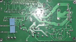
What does this relay do ?
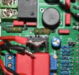
What does this relay do ?
I thought the board we were working on was OK now, and that it just needed soak testing with a fuse in case anything was amiss.
What does this relay do ?
It's a speaker protection thing I believe.
Sorry about the s**ty pics. I also tested a DAC and a headamp today.
The headamp worked fine atleast.
DAC had sound but weak and drowned in noise.
I have a third built board (TA2022) intended to be used in stereo for the mids/highs in my dipoles. I'll test that one too to see if it works ok atleast.
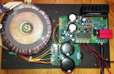
While I'm asking questions and getting help(thank you very much mate!), I thought I'd ask if Y-splitting a center tap on a transformer to be used with dual bridge rectifiers is ok?
Just me not wanting to re-work the extra capacitance board I made for the stereo TA2022 as I thought I remembered the toroidal transformer for that having real dual secondaries so to speak.
Attachments

The Y splitting doesn't look right because the two DC rails created are not floating. That means you can't just connect them together to create a dual supply. Doesn't doing what you have done just effectively make it all a half wave rather than full wave set up.
You would have to draw it all out to see what the current paths were but it doesn't look right. You need a transformer with two individual windings to do what you seem to have done.
You would have to draw it all out to see what the current paths were but it doesn't look right. You need a transformer with two individual windings to do what you seem to have done.
The Y splitting doesn't look right because the two DC rails created are not floating. That means you can't just connect them together to create a dual supply. Doesn't doing what you have done just effectively make it all a half wave rather than full wave set up.
You would have to draw it all out to see what the current paths were but it doesn't look right. You need a transformer with two individual windings to do what you seem to have done.
Ok, figured it might be wrong, so I asked before powering the thing up.
I simply split the center tap, ran one with one of the secondaries to one bridge, the other with the other secondary to the other bridge.
It's simple enough to remove the bridges from the cap board and use a single, chassi-mounted, bridge instead.
I'll fix that then.
I've got a few beefy chassi mount bridge rectifiers at home.
I hope the other board works, then I can put that in the BTL amp for now and use the faulty one in the stereo amp when I get it working. I've got some TA2022 IC's and extra relay's etc so hopefully I'll get it working eventually.
I've got a few beefy chassi mount bridge rectifiers at home.
I hope the other board works, then I can put that in the BTL amp for now and use the faulty one in the stereo amp when I get it working. I've got some TA2022 IC's and extra relay's etc so hopefully I'll get it working eventually.
Well, I moved the board meant as a stereo amp to the BTL chassis, hooked it up and it works fine. I can't seem to trim down DC offset though, it's very high at around 460mVdc.
Time for me to take a painkiller now anyway and continue tomorrow with a fresh head and body.
Time for me to take a painkiller now anyway and continue tomorrow with a fresh head and body.
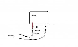
Just for curiosity try something like this for checking the offset. Values aren't critical at all.
I'll try that today and report back results.
Didn't get around to testing that yesterday as we went shopping for tiny clothes 😀
Hopefully I'll get around to it today.
Hopefully I'll get around to it today.
Before soldering up the "jig" you posted, I tried again with the trimmers.
With power off I turned them fully CCW, then ten turns CW for both to see what happend with the DC offset. It stayed at around 440-455mVdc, slowly rising I think.
Had it on for maybe 30s trying a turn in each direction on each trimmer...no difference what so ever in the DC offset.
Then I, out of curiousity, looked at the resistor that got swollen on another board. I THINK this one is starting to bulge as well... and maybe the other one next to it? could be optical illusion though.
Attachments
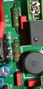
As long as the resistors are not to hot then they should be fine, and those look like metal oxide types which can withstand very high temperature. Just measure the voltage across them and calculate the wattage.
As long as the resistors are not to hot then they should be fine, and those look like metal oxide types which can withstand very high temperature. Just measure the voltage across them and calculate the wattage.
Will do. A project for tomorrow though.
- Status
- Not open for further replies.
- Home
- Amplifiers
- Class D
- TA2022 LJM swollen resistor, why?