Hi All
I have made a new thread because of the tapped horn is not a T-TQWT.
I put here the T-TQWT thingies.
I have done a learning process, unfortanely akabak was less difficult then I thought and so I have done some simulations in hornresp and akabak.
Some things.
the stuffing in akabak is alone alowed when a duct, with a waveguide I get a error, the T-TQWT has a flare after S2 and so exported file is a waveguide without stuffing.
The filter I can put in script with akabak, do this also include resistance of coils? I cab also make a coil, capacitor in the script where I can put resistence in Rs.
The T-TQWT has two versions, bjorno has build the most 1/4 tapped T-TQWT
I need a big S1 and S2, the woofer is deep, and so need 33 x 20 cm including clearance behibd the woofer of 2 inch like bjorno advise so I did.
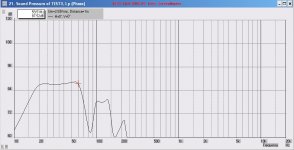
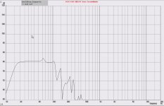
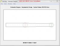
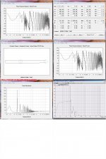
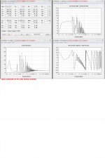
When simulated in hornresp I get a big peak on cutoff 18 hz and on 110 herz, the first I can stuff, it go right (see photo,s) the upper peak is less because I can not stuff S2 in akabak, for as far I do not now yet.
I hope that I am a little clear here.
Oracle virtual box, akabak do fine but hornresp give runtime error 62 input past end of file, I will do set windows 7 32 bit soon, there works akabak.
kees
I have made a new thread because of the tapped horn is not a T-TQWT.
I put here the T-TQWT thingies.
I have done a learning process, unfortanely akabak was less difficult then I thought and so I have done some simulations in hornresp and akabak.
Some things.
the stuffing in akabak is alone alowed when a duct, with a waveguide I get a error, the T-TQWT has a flare after S2 and so exported file is a waveguide without stuffing.
The filter I can put in script with akabak, do this also include resistance of coils? I cab also make a coil, capacitor in the script where I can put resistence in Rs.
The T-TQWT has two versions, bjorno has build the most 1/4 tapped T-TQWT
I need a big S1 and S2, the woofer is deep, and so need 33 x 20 cm including clearance behibd the woofer of 2 inch like bjorno advise so I did.
When simulated in hornresp I get a big peak on cutoff 18 hz and on 110 herz, the first I can stuff, it go right (see photo,s) the upper peak is less because I can not stuff S2 in akabak, for as far I do not now yet.
I hope that I am a little clear here.
Oracle virtual box, akabak do fine but hornresp give runtime error 62 input past end of file, I will do set windows 7 32 bit soon, there works akabak.
kees
Attachments

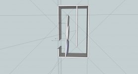
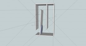
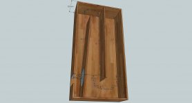
Well I have practise and practise and praktise to fold, but I am not a fan of sketchup it do not always what I want, except if I follow exactly program protocol.
We call that in holland eigenwijs programma.
Oke if someone wil take a look at the fold and the hornresp export I can learn some about that folding.
thanks.
We call that in holland eigenwijs programma.
Oke if someone wil take a look at the fold and the hornresp export I can learn some about that folding.
thanks.
Attachments
Well I have practise and practise and praktise to fold, but I am not a fan of sketchup it do not always what I want, except if I follow exactly program protocol.
We call that in holland eigenwijs programma.
Oke if someone wil take a look at the fold and the hornresp export I can learn some about that folding.
thanks.
Where is the input screen(s) or scripts referring to this thread?...
b🙂
Hi Bjorn
I have put here some sample tests for learning akabak, what go well, I do now how to add things like resistors coils.
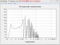
But I do not yet now for shure in hornresp how to do the L12 and L34, I use a duct behind the woofers like you do, and a tapered L23, if I do a hornresp simulation without stuffing I see a peak above 100 Hz and one on cutoff of foer example 20 Hz, in akabak I see the this go away when stuffed the duct part S1 and S2 as you can see in previeus post, here I have input a filter 18dB octave 100 Hz what do make bandwith from 20 to 100 Hz or even higher the second graph is a T-TQWT with one woofer with woofer on the end of pipe and not on 1/4 give smalled bandwith but see also good, I have a open baffle what wil be used with the subs. I do how hornresp works also th L34 and L12 but only the T-TQWT has sometimes a endpad I don,t understand to translate in a box. I hope the picture are the right way, or close what to do
these are the last nuts to break for me.
I have search your designs, and my next and last question is sometimes I see the woofer stick out of S4 in the version with two woofers, do you end L23 between the woofers, then I need a L12 of minimun 32 cm if you do lift opening S4 then L12 is 17 cm, see picture above post my mening is L12 for the first woofer 17 cm gif best results but then
woofer sticks out on hornresp schematic S4.
This is I think al I do need from the past postings now I can myself do the design, I go make test simulations and tryouts first I come where I want to be on my own now.
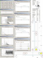
I can input all filters in akabak, I have even tryed a notch in it I get the nodes now no problem, the standart filtering from the menu is lossless I think, and so I do set caps and coils with nodes and resistance myself, see akabak cript of i did good.
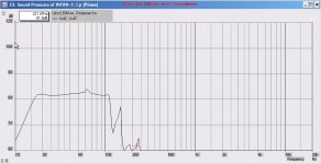
If you look at picture 3 in previeus post, you see the peaks low and high, whit stuffing and filtering it looks like on picture in the middle.
The sketchup try box is also to learn how to fold, I go use the folding schematic of
I hope you get my english I do my best.
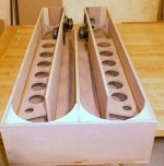
two foto,s who ive the picture, it Just example not final.
here are the script of the T-TQWT with two woofers, looks oke for me, from 18 to 110 nice line. on foto two there is little peak left on 53 hz, but can be because it has to be little more suffing then only duct.
Thanks for all the help.
I have put here some sample tests for learning akabak, what go well, I do now how to add things like resistors coils.
But I do not yet now for shure in hornresp how to do the L12 and L34, I use a duct behind the woofers like you do, and a tapered L23, if I do a hornresp simulation without stuffing I see a peak above 100 Hz and one on cutoff of foer example 20 Hz, in akabak I see the this go away when stuffed the duct part S1 and S2 as you can see in previeus post, here I have input a filter 18dB octave 100 Hz what do make bandwith from 20 to 100 Hz or even higher the second graph is a T-TQWT with one woofer with woofer on the end of pipe and not on 1/4 give smalled bandwith but see also good, I have a open baffle what wil be used with the subs. I do how hornresp works also th L34 and L12 but only the T-TQWT has sometimes a endpad I don,t understand to translate in a box. I hope the picture are the right way, or close what to do
these are the last nuts to break for me.
I have search your designs, and my next and last question is sometimes I see the woofer stick out of S4 in the version with two woofers, do you end L23 between the woofers, then I need a L12 of minimun 32 cm if you do lift opening S4 then L12 is 17 cm, see picture above post my mening is L12 for the first woofer 17 cm gif best results but then
woofer sticks out on hornresp schematic S4.
This is I think al I do need from the past postings now I can myself do the design, I go make test simulations and tryouts first I come where I want to be on my own now.
I can input all filters in akabak, I have even tryed a notch in it I get the nodes now no problem, the standart filtering from the menu is lossless I think, and so I do set caps and coils with nodes and resistance myself, see akabak cript of i did good.
If you look at picture 3 in previeus post, you see the peaks low and high, whit stuffing and filtering it looks like on picture in the middle.
The sketchup try box is also to learn how to fold, I go use the folding schematic of
I hope you get my english I do my best.
two foto,s who ive the picture, it Just example not final.
here are the script of the T-TQWT with two woofers, looks oke for me, from 18 to 110 nice line. on foto two there is little peak left on 53 hz, but can be because it has to be little more suffing then only duct.
Thanks for all the help.
Attachments
Last edited:
Hi Bjorn I have now did a project who I go try to make, a T-TQWT in the zip is all
the thingies you need for a look at it, Now I can play with al this stuff.
regards
the thingies you need for a look at it, Now I can play with al this stuff.
regards
Attachments
Last edited:
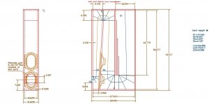
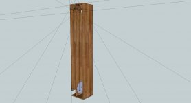
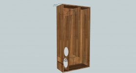
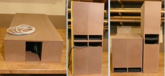
here there is all fo the box in one picture, I need some advise about what to do with the
woofer outside the horn end, how to implement.
thanks.
Hi Kees,
Here is a HR simulation where one of the shown Drivers appears on the 'out-side' of the enclosure but this should not be the case in the reality:
b🙂
Attachments
Hi Bjorno
I did see on some designs that the port is in the middle of the lower speaker who do excactly what you mean, because it is a turn there.
S4 center appears then in middle front of the lower woofer independent of how long S4 is opening is only in panel.
I have to use to it, it is defferent way then closed or vent box who is simple.
Thanks
kees
Hi Bjorn
Can you give me points for this design with two visatons, did I go oke now, after a time of learning and find easy ways.
Wel the easy way is not so possible folding takes time and I am a little critical myself, so I have done the box as precisely as possible to get close to hornresp.
see the pictures of it, a very nice graph I think.
So hope I am granted by you haha.
Attachments
HR input for 2 drivers
Hi there K: Your HR SPL graph looks great, and should operate as you intended, however, your input data shown in the screen shows TH 1. Your text and sketch-up show you intended to install two (2) Visaton drivers. Recommend you check the displacement graph (for Xmax) and compare the maximum to the Visaton driver data sheet for Xmax. If you are at or below the manufacturers recommended Xmax, you can proceeed with one (1) driver. However, if the Xmax is exceeded for one driver, go back to HR, Tools, driver arrangement and change it to 2 series, meaning 2 drivers wired in series....return to input screen, TH 2S should be on the screen...hit calculate an recheck for Xmax for 2 drivers series. Hope you construct this sub unit. ....regards, Michael
Hi Bjorn
Can you give me points for this design with two visatons, did I go oke now, after a time of learning and find easy ways.Wel the easy way is not so possible folding takes time and I am a little critical myself, so I have done the box as precisely as possible to get close to hornresp. see the pictures of it, a very nice graph I think.......
Hi there K: Your HR SPL graph looks great, and should operate as you intended, however, your input data shown in the screen shows TH 1. Your text and sketch-up show you intended to install two (2) Visaton drivers. Recommend you check the displacement graph (for Xmax) and compare the maximum to the Visaton driver data sheet for Xmax. If you are at or below the manufacturers recommended Xmax, you can proceeed with one (1) driver. However, if the Xmax is exceeded for one driver, go back to HR, Tools, driver arrangement and change it to 2 series, meaning 2 drivers wired in series....return to input screen, TH 2S should be on the screen...hit calculate an recheck for Xmax for 2 drivers series. Hope you construct this sub unit. ....regards, Michael
Ahh yes you are right, it is one visaton, it is a test of how I have to fill in dimensions.
Two visatons give a big box, my intention was how it is best to make the box in sketchup, I have to go through a learning process, I hope you find that I succeeded.
I do recalc the folding for one speaker,, I did try two but then the box gets extreme big, because of the big vas of the visatons, so I do one or isobaric try.
thanks for the reply.
Last edited:
make a double box 😀
Nice thing, but big? I do make the infinity box, I am drawn now, with double 12 inch infinity reference woofers.
And the visatons afcourse so I can sell them.
thanks for reply.
kees
Don't forget you can fold them - put them side by side, make doubles, single fold boxes, etc.
How bigThe forum guys deigned them.
What drivers are used? Where can I find these designs? THANKS.
- Status
- Not open for further replies.
- Home
- Loudspeakers
- Subwoofers
- T-TQWT subwoofer