Hi all,
I was reading Slone's book on amp construction and I read I passage I cannot understand. I quote it here (with some cuts and modifications) hoping you can confirm what he writes and explain me why it's true. Or the other way around..
A common mistake is forming a "T" network to connect the rail conductor, caps, and rectifier output. In other words, a splice is made in the conductor connecting bridge output and the rail conductor. Then a single conductor is run from this connection point to the caps. [...] This is wrong! A T connection will cause a significant voltage drop across the single wire leading to the caps and the 2 connection points on either end. This voltage drop will look like an increase of ripple content on the rail supplies.
Is this actually true? And why?
Thanks all
AC
I wonder what is meant by significant. A few microvolts maybe and that will not matter. Ripple on a balanced amplifier supply does not really matter as long as the rail voltages do not equal the output voltages.
Any wire, and hence resistance, in series with the caps can be very bad indeed. Supply caps are charged at quite high currents for only a small period of time at the beginning of each (rectified) cycle so even a small resistance can result in noticeable voltage spikes on the power supply rails. This is why "Star" wiring is usually udes.
In a PSU you must regard every connection as a resistance. This is because it is a resistance. If you have amps of current in charging pulses, then it does not take much resistance to develop a significant voltage drop. Millivolts are easily seen, because connections are typically in the milliohm range.
You can't avoid capacitor ESR, but there is no need to add unnecessary wiring resistance too.
As a general rule, mistakes in PSU grounding are more serious than mistakes in rail wiring.
You can't avoid capacitor ESR, but there is no need to add unnecessary wiring resistance too.
As a general rule, mistakes in PSU grounding are more serious than mistakes in rail wiring.
I've seen PSU designs with resistance everywhere:
e.g. (just by googling "audio psu"):
psu bleeding resistor - Cerca con Google
-> R1 (2.2 kOhm)
-> R3 (1 Ohm)
-> R5 (0.5 Ohm)
So what game are we playing here? To avoid 10cm of thick wire but use resistors?
Some people use also inductors in the PSU, and that's a lot of wire too..
Is there a science behind all this? I'm very confused..
Use a critical choke input supply and you will mitigate this issue. Smooth constant conduction beats high current charging pulses. You'll need a higher voltage transformer to get the same output, but it's worth it IMO.
it's the neverending dilemma: science vs superstition.. 😉
and unluckily also books can be written using the wrong source of the above two..
of course with internet you have a much higher probability to find information which is based on superstition than in books..
and by the way.. audio is often seen as something subjective more than objective.. so to me subjective often sound as well like superstition..
tent:wq
Surprising as it may seem, resistance does a useful job in the right places and a bad job in the wrong places. The art/science of electronic design is partly about knowing which is which.grandemahatma said:So what game are we playing here? To avoid 10cm of thick wire but use resistors?
Some people use also inductors in the PSU, and that's a lot of wire too..
Is there a science behind all this? I'm very confused..
You will find some people 'design' on the basis of mantra (e.g. "capacitors are bad"). You may ignore them; I do, except when I am arguing with them.
Last edited:
Surprising as it may seem, macaroni does a useful job in the right places and a bad job in the wrong places.
But also:
Surprising as it may seem, farting loudly does a useful job in the right places and a bad job in the wrong places.
Although I have enough experience in macaroni and farts, I'm still looking for a way to access scientific information about PSU design..
Can you help me?
Thanks
AC
But also:
Surprising as it may seem, farting loudly does a useful job in the right places and a bad job in the wrong places.
Although I have enough experience in macaroni and farts, I'm still looking for a way to access scientific information about PSU design..
Can you help me?
Thanks
AC
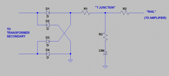
Slone is referring to the schematic below. R1, R2, R3 are the unavoidable wiring resistances, lead resistances, and connection resistances of the high current paths between power supply rectifier, filter capacitor, and amplifier "rail".
He warns readers that a T junction configuration will make resistor R3 larger, and this is undesirable.
You can do a back of the envelope calculation to estimate the maximum allowable value of (R2 + R3).
He warns readers that a T junction configuration will make resistor R3 larger, and this is undesirable.
You can do a back of the envelope calculation to estimate the maximum allowable value of (R2 + R3).
- Assume the loudspeaker (load) impedance is 4 ohms
- Assume you want (R2+R3)'s contribution to output distortion, to be -90 dB below signal
- Assume your amplifier has the exact same PSRR curve as the Blameless amplifier in Douglas Self's book APADH 5th edition, Figure 9.10 (p.292). Namely, -45 dB PSRR
Attachments
Eh eh, is there a way to access this information without being eligible for a cum laude in electrical engineering?
I've been reading this forum for quite some time but I got the feeling that most of the people writing here do believe in magic.. And I'm not sure how much I can rely on this book neither..
I've been reading this forum for quite some time but I got the feeling that most of the people writing here do believe in magic.. And I'm not sure how much I can rely on this book neither..
It only takes 4 years to earn a degree in electrical engineering, at least in the US. This includes all of the additional required classes that aren't EE specific (literature, foreign language, political science, fine arts, athletics, etc). An enthusiastic and motivated autodidact could probably work through the entire EE curriculum in 2.5 to 3 years, without paying a penny of tuition. If he/she has already learned calculus and diff-eq, even less time.
Eh eh, is there a way to access this information without being eligible for a cum laude in electrical engineering?
I've been reading this forum for quite some time but I got the feeling that most of the people writing here do believe in magic.. And I'm not sure how much I can rely on this book neither..
You can definitely rely on Horowitz & Hill and if you read it closely and work through the exercises you will gain a very good working knowledge of the science side of audio electronics. I got my copy off eBay's books auction site for about $20...best money you can spend on this hobby!
I realise this is only intended to be a 'back of envelope' calculation, but even that should be based on some sound theory. You seem to be combining ripple, PSRR and distortion all in one big estimate when they need to be kept separate. R3 increases ripple, but by how much depends on assumptions about charging pulses.transistormarkj said:You can do a back of the envelope calculation to estimate the maximum allowable value of (R2 + R3).
Assume the loudspeaker (load) impedance is 4 ohms
Assume you want (R2+R3)'s contribution to output distortion, to be -90 dB below signal
Assume your amplifier has the exact same PSRR curve as the Blameless amplifier in Douglas Self's book APADH 5th edition, Figure 9.10 (p.292). Namely, -45 dB PSRR
You want 90 dB of s/n and the amplifier's PSRR gives you 45 dB of it. Then you need 45 dB more attenuation from (R2+R3) to output. That's a factor of 10^(45/20) = 178X. So you want (R2+R3) to be 178X smaller than 4 ohms. Thus you want (R2+R3) < 0.022 ohms, in this example calculation.
You don't need an EE degree to understand the basics of PSUs. The maths and science understood by a bright teenager is sufficient to make a start. However some effort is needed, as for any field of study. The more advanced aspects of PSU design might go beyond a modern EE degree.grandemahatma said:Eh eh, is there a way to access this information without being eligible for a cum laude in electrical engineering?
I've been reading this forum for quite some time but I got the feeling that most of the people writing here do believe in magic.. And I'm not sure how much I can rely on this book neither..
Some people on here, as any other website, do seem to believe in magic; fortunately, most do not.
H&H is reliable.
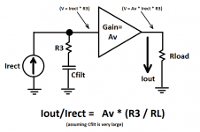
Hi DF96, you're right, I did a lot of handwaving and not much math. I wrote "distortion" and "signal-to-noise" when, in fact, I was simply estimating the Ripple-Current gain. I "derived" the transfer function from ripple current input, to loudspeaker current output, by appeal to intuition. I'll derive it again here, this time with less handwaving. A block diagram is attached.
The power supply rectifier(s) charge the power supply filter capacitance Cfilt. Unfortunately, the amplifier builder did not heed Randy Slone's warnings, and so an unwanted series resistance R3 is present. An unwanted noise voltage Vunwanted = (Irect * R3) is present. Notice that if R3 = zero then Vunwanted is also zero. (I've assumed that Z(Cfilt) << Z(R3) for mathematical simplicity)
The transfer function from supply_rail, to amplifier_output, is modeled as a gain block whose voltage gain is "Av". This, in fact, is the amplifier's power supply rejection ratio: Av = PSRR. The loudspeaker connected to the amplifier output converts voltage to current: Iout = Vout / Rload. We now have everything we need to write the expression for the Ripple-Current gain
So if you want your amplifier's Ripple-Current gain to be -90 dB or less, and if your amplifier has got a PSRR of -45 dB like the Blameless amp in Self's book, then you want (R3/RL) to be -45 dB. (R3 < (RL / 178)).
A similar block diagram and a similar analysis applies when the amplifier is operating Class AB or Class B, and the rail currents are time-varying. Now the rail resistor R2 enters the model, and a different noise current is injected at a different place. An expression for the Ripple-Current gain in this second case, is left as an exercise 🙂 I observe, en passant, that it may be easier to reduce the magnitude of rectifier current pulses (case 1), than to reduce the magnitude of Class-AB rail current pulses (case 2). If so, the (R2+R3) ripple current gain expression may be the more useful of the two.
. . .
The power supply rectifier(s) charge the power supply filter capacitance Cfilt. Unfortunately, the amplifier builder did not heed Randy Slone's warnings, and so an unwanted series resistance R3 is present. An unwanted noise voltage Vunwanted = (Irect * R3) is present. Notice that if R3 = zero then Vunwanted is also zero. (I've assumed that Z(Cfilt) << Z(R3) for mathematical simplicity)
The transfer function from supply_rail, to amplifier_output, is modeled as a gain block whose voltage gain is "Av". This, in fact, is the amplifier's power supply rejection ratio: Av = PSRR. The loudspeaker connected to the amplifier output converts voltage to current: Iout = Vout / Rload. We now have everything we need to write the expression for the Ripple-Current gain
- Ripple-Current gain = Iout/Irect = PSRR * (R3 / RL)
So if you want your amplifier's Ripple-Current gain to be -90 dB or less, and if your amplifier has got a PSRR of -45 dB like the Blameless amp in Self's book, then you want (R3/RL) to be -45 dB. (R3 < (RL / 178)).
A similar block diagram and a similar analysis applies when the amplifier is operating Class AB or Class B, and the rail currents are time-varying. Now the rail resistor R2 enters the model, and a different noise current is injected at a different place. An expression for the Ripple-Current gain in this second case, is left as an exercise 🙂 I observe, en passant, that it may be easier to reduce the magnitude of rectifier current pulses (case 1), than to reduce the magnitude of Class-AB rail current pulses (case 2). If so, the (R2+R3) ripple current gain expression may be the more useful of the two.
. . .
Attachments
You still appear to be equating load current (mainly signal) to ripple current (mainly ripple), so merely expanding and giving more detail for a flawed calculation. In reality the ripple current will be larger than the peak signal current, by a factor which depends on things like reservoir capacitor size but will often be in the range 3-5.
Sorry to jump in again with critics.. I highly appreciate the explanations that Transistormarkj gives. Correct or wrong, I think this is the way to go. By reading them one gets an idea on where to start looking for information.
On the other hand I don't see the point of DF96's posts: I know it costs more efforts to explain what you mean, but unless you provide a quantitative information you post are useless to anybody knowing less than you.
.."depends on things like reservoir capacitor?" Oh yeah? why? how? Does it depend also on things like something else?
Please don't take it personally, I'm just trying to figure out things.
Cheers
AC
I can't explain the complex relationship between cap size and charging current pulse size in a single post - it requires solving differential equations with non-analytic solutions so simulation is the only reasonable option. There are whole threads about this subject (and whole textbook chapters). I did give quantitative information: "3-5" is a reasonable estimate. As I said, transistormarkj was mixing up things which are different so his estimate was rather off the mark.grandemahatma said:On the other hand I don't see the point of DF96's posts: I know it costs more efforts to explain what you mean, but unless you provide a quantitative information you post are useless to anybody knowing less than you.
.."depends on things like reservoir capacitor?" Oh yeah? why? how? Does it depend also on things like something else?
You appear to be at the stage where you can innocently ask a question without realising just how complex the correct answer will be. We were all there once. Be patient. Read the book. Learn how PSUs work.
Buy 'The Art of Electronics' by Horowitz and Hill. Read it.
OK, thanks for the pointer, I just ordered it, and will read.
- Status
- Not open for further replies.
- Home
- Amplifiers
- Power Supplies
- T splices in the PSU: that bad?