carlosfm said:
Mmmm...
You use an input buffer, right?
So, the amp always sees a previous stage.
Do you have a resistor from input to ground? If you have an input buffer, put the resistor before it.
Thanks for your patience Carlos,
Right you are. I realized this after I wrote the previous post (smacking forehead). I hadn't installed a pot, so no input resistor to ground. Fine when hooked up to the preamp, but not so good open. The other amp, of course has a volume control pot, so always a path to ground.
Sheldon
I have built another IGC with T-Network feedback resistors.
Same resistor values:
Input 22K
Feedback 10 K + 10K with 100R to ground
10K from NI to ground.
On one channel I started with 102 mV and I can trim that down to 15 mV with the trimmer set to minimum resistance.
On the other channel, I started with 20 mV and have got that down to 2 mV with a value of 7K3 between NI and ground.
Quite a difference! 😱
Any comments T-Networkers?
My IGC ( LM3886T) with T network uses a 100K feedback resistor
2.2K and 75 ohms at the output and 100K to ground from the positive input. Offset was 12mV and -9.9mV. Resistors were not selected.
Guess I got lucky.
Cheers.
2.2K and 75 ohms at the output and 100K to ground from the positive input. Offset was 12mV and -9.9mV. Resistors were not selected.
Guess I got lucky.
Cheers.
My IGC ( LM3886T) with T network uses a 100K feedback resistor 2.2K and 75 ohms at the output and 100K to ground from the positive input. Offset was 12mV and -9.9mV. Resistors were not selected.
Ashok, this sounds like a very strange T-Network to me!
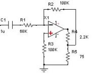
You say it is a 100K feedback resistor but for a T-network, there are three resistors, two in series; and one from their junction to ground. Can you clarify your arrangement for us please? 😕
Hi Nuuk,
I've made a quick drawing. Hope this makes things clear.
The drawing shows a generic opamp. This should be the LM3886T.
I've left out all the other parts.
Cheers,
Ashok.
The jpeg image is too small. Just click on it and it comes up large enough to see details.😡
I've made a quick drawing. Hope this makes things clear.
The drawing shows a generic opamp. This should be the LM3886T.
I've left out all the other parts.
Cheers,
Ashok.
The jpeg image is too small. Just click on it and it comes up large enough to see details.😡
Attachments
I've made a quick drawing. Hope this makes things clear.
Yes thanks Ashok. But how did you arrive at those values?
I replaced the LM3875 that orignally had 102 mV of offset with 10K NI to ground with another chip and the same resistors. This one gave 32 mV at 10K.
I have now replaced both trimpots with 7K5 resistors and have 3 mV on one channel and 5 mV on the other. I am running that amp to burn it in before I make a final decision on the T-network versus a single resistor but one thing is confirmed with both the T-network IGC's that I have built, there is more detail! 😉
I note that this thread has gone a bit quiet - is nobody else trying the T-network?

I'm Planning On It!
Nuuk,
I am planning on building a VBIGC with t-network "real soon now". My original plan was to take two of the non-inverted amp channels I have already built and modify them with valve buffering as described in another thread.
However after following this thread and visiting both the Decibel Dungeon and Joe's valve buffering site I've decided to build new amps in inverted configuration with valve buffering. My current plan is to go with mono-blocks but that is not written in stone yet.
I am awaiting delivery of final parts to start construction of a valve pre-amp and plan to use the VBIGC/T with the pre-amp.
I'm also thinking of designing a pc board combining valve buffering, t-network and zobel for the LM3875. The problem there is I'm a pc design newbie so that might take quite a while!
😀
Nuuk said:...I note that this thread has gone a bit quiet - is nobody else trying the T-network?
Nuuk,
I am planning on building a VBIGC with t-network "real soon now". My original plan was to take two of the non-inverted amp channels I have already built and modify them with valve buffering as described in another thread.
However after following this thread and visiting both the Decibel Dungeon and Joe's valve buffering site I've decided to build new amps in inverted configuration with valve buffering. My current plan is to go with mono-blocks but that is not written in stone yet.
I am awaiting delivery of final parts to start construction of a valve pre-amp and plan to use the VBIGC/T with the pre-amp.
I'm also thinking of designing a pc board combining valve buffering, t-network and zobel for the LM3875. The problem there is I'm a pc design newbie so that might take quite a while!
😀
Hi Sherman,
You seem to have a choice between single supply stereo and independant monoblocks . Stick to monoblocks . Apart from monoblocks sounding better the LM chip might give you earthing problems on one channel depending on your input earthing scheme and some odd behaviour at the output.
The effects are a very low levels but neverthless, avoidable.
I suggest you keep the valve outside ( separate pcb ) in case you have problems with it .
You need to be VERY careful about grounding schemes or you will see 120Hz ripple nightmares!
Cheers.
ashok said:Hi Sherman,
You seem to have a choice between single supply stereo and independant monoblocks ....
I suggest you keep the valve outside ( separate pcb ) in case you have problems with it .
You need to be VERY careful about grounding schemes or you will see 120Hz ripple nightmares!
Cheers.
Thanks for this input! I already have the transformers, 2 CT toroids to power the LM3875s, 2 12.6 CT transformers for the filament and 2 25VAC CT that I will use to get the +-35VDC for the valve. So plenty of transformers to make 2 independent monoblocks.
Of course each amp will then only use 1/2 the 6922. I thought I might wire the amps so that one uses the "first" triode in the envelope and the other uses the "second" triode in the envelope. That way if a triode goes bad in a tube I can just swap tubes between the amps.
Keeping the valve on a different board sounds like a better idea than trying to do it all on one (which was what I was trying to do). I'll change my layout. It would be more flexible also with the ability to then mount the valve anywhere in the chassis relative to the amp, tube out, tube inside etc.
I'm aware of the potential issues with grounding having built a couple of tube amps and also having screwed up the grounding in the first hardwired GC I built. Nothing but 120Hz hum until I got that sorted out! Of course not being experienced with pc board design I'm sure I can find a few ways to screw it up.
😉
I have done my first T network LM3875 GC.
Resistor values:
Input 20K
Feedback 10 K + 10K with 100R to ground
10K from NI to ground.
5% precision resistors
I have about 58mV of offset (sometimes 44mV 🙄 )
That beats the other NI GC I have made.
Thanks guys for your active research for sound Nirvana 😉
Resistor values:
Input 20K
Feedback 10 K + 10K with 100R to ground
10K from NI to ground.
5% precision resistors
I have about 58mV of offset (sometimes 44mV 🙄 )
That beats the other NI GC I have made.
Thanks guys for your active research for sound Nirvana 😉
yopi3622 said:I have done my first T network LM3875 GC.
Resistor values:
...
I have about 58mV of offset (sometimes 44mV 🙄 )
That beats the other NI GC I have made.
Thanks guys for your active research for sound Nirvana 😉
Is this GC with the t-network inverted or non-inverted?
10K from NI to ground.
So, your amp plays over the inverting input. Isn't it?
That beats the other NI GC I have made.
😎
Thanks guys for your active research for sound Nirvana
Joe Rasmussen: where are you? In vacation?
Thanks, yopi!
Franz
Sorry, I have made a little mistake.
All my previous GCs were IGC.
The T feedback is a IGC too.
"That beats all my previous IGC" 😀 (they were around 90mV)
Yopi
All my previous GCs were IGC.
The T feedback is a IGC too.
"That beats all my previous IGC" 😀 (they were around 90mV)
Yopi
For those having just Rin between the input buffer and the LM3875 pin8.... do you think we would have better noise figure using a T attenuator in place of the input resistor ???
This would make a T feedback T Rin BIGC !!
😀
This would make a T feedback T Rin BIGC !!
😀
That beats all my previous IGC" (they were around 90mV)
C'est le ton qui fait la musique, n'est pas?
It is the tone, making the music...
And does it beat your other IGC's soundwise?
Courious
Franz
C'est le ton qui fait la musique, n'est pas?
Bien vu Franz 😉
And does it beat your other IGC's soundwise?
I cannot objectively answer this question because the gain changed, my layout changed, and my power changed too 😎
But yes!! I have a better sound (I had harshness before).
Why is it so much better?
In the meantime, I breaked my head with the question, why the t-net for feedback is sounding worlds better than the traditional feedback.
I think, I found the simple answer.
And you?
Before I will post my explanation, I would like to read some other explanations, please!
Franz
In the meantime, I breaked my head with the question, why the t-net for feedback is sounding worlds better than the traditional feedback.
I think, I found the simple answer.
And you?
Before I will post my explanation, I would like to read some other explanations, please!
Franz
Franz G said:
Joe Rasmussen: where are you? In vacation?
Thanks, yopi!
Franz
Sorry Franz, actually IF I had been on vacation, then you'd have heard from me sooner. Actually working about 16 hours a day, although it should ease up around the weekend. Need to read back on posts and get up-to-date. Promise I'll do that asap.
My JLTi Mark 2 is under development, also I'm between two jobs (essentially doing BOTH at the moment). Going overseas at the end of November, got more loose strands than my hairdo to tie up.... you get the picture.
Much rather spend time here... sigh.
Joe R.
Back emf ?
Well , this has been bugging me also. So after looking hard at the circuit for a long time , one simple thing that I noticed was that the back emf from the speaker fed back to the input of the amp is now reduced due to the voltage divider.
The extreme situation of this is an amplifier with no overall negative feedback.
Another reason why amplifiers with no negative feedback can potentially sound better than feed back types ?
Cheers,
Ashok.
I think, I found the simple answer.
Well , this has been bugging me also. So after looking hard at the circuit for a long time , one simple thing that I noticed was that the back emf from the speaker fed back to the input of the amp is now reduced due to the voltage divider.
The extreme situation of this is an amplifier with no overall negative feedback.
Another reason why amplifiers with no negative feedback can potentially sound better than feed back types ?
Cheers,
Ashok.
one simple thing that I noticed was that the back emf from the speaker fed back to the input of the amp is now reduced due to the voltage divider.
Bingo!
Thats exactly, what I think! The voltages at resonance frequencies, flowing back from the speaker to the input, are drastically reduced by the voltage divider.
So, distortion caused by the speakers and fed back to the input is reduced.
This must be the most important effect of the t-network (despite of the lower Z and higher possible input-Z).
Franz
- Status
- Not open for further replies.
- Home
- Amplifiers
- Chip Amps
- T-network: the better feedback solution?