Chocoholic, Great work here
What software are you using to measure the THD.
I would like to measure the THD on my D amp, It is running 43 volt rails at 1.35 mhz switching frequency with 15uh output choke and .22 uf cap.
an OPA2134 performs the audio correction
A low side comparator drives the output transistors IRFB4212's
(high side is discreet as well)
I would like to test this amp's Distortion levels.
15mv offset with 400mv switching residual at output
Hi Kanvar,
the zobel at the output is not needed for stability in the chosen PID parameter set - in the moment I am using a low loss zobel of 0.33uF and 1R6 for shaping the residuals and squeezing the K3 below -96dB....
Hi Stocktrader,
I am using the free Right Mark software RMAA 5.5 (I am still with XP....).
My soundcard is an external USB card, E-MU Tracker Pre.
...upgraded the soundcard with OPA2134 and gained some few dB in distortion (loop back check with only a wire as DUT).
In any case you should use a passive low pass at the input of your sound card, when measuring class D amps, at least 2nd order. This avoids irritations of the sound card, which can happen from the carrier residuals.
@Stocktrader:
I guess you are talking about this amp
http://www.diyaudio.com/forums/class-d/127096-i-got-my-class-d-working.html
Curious on further measurement results, not just THD but step response and clipping recovery as well.
In any case, my congratulation to your design/build, enjoy RMAA.
I guess you are talking about this amp
http://www.diyaudio.com/forums/class-d/127096-i-got-my-class-d-working.html
Curious on further measurement results, not just THD but step response and clipping recovery as well.
In any case, my congratulation to your design/build, enjoy RMAA.
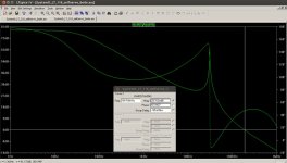
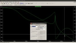
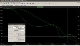
For more details on Kanwar's question, I am adding the bode plots of the chosen PID loop gain for three situations.
- No zobel, no load ==> phase margin is 47°
- With my shaping zobel consisting of 330nF and 1R6, but still no load ==> phase margin is 49°
- With shaping zobel and 2R load ==> phase margin is 58°
With compromising step response and less phase margin, one could of course go for higher loop gain, but I prefer it this way.
Attachments
Most school books (and Universities) do not teach this extended criteria for stability.
It describes positive phase margin for systems where the phase has multiple zero crossings and still the criteria for stability is that the phase margin needs to be positive only at the relevant frequency, where the loop gain crosses 0db.
I agree that this criteria is sort of counterintuitive.
Control theory simply is beyond healthy human imagination....
In the mean time I fully trust on this criteria, because I found one book, which mentions this criteria + transient analysis of PSpice also matches + the real build did not present unpleasant surprises.
In my references I am listing a book about control theory, which highlights this extended criteria for stability in chapter 8.5.5
J. Lunze:
Regelungstechnik 1
DOI 10.1007/978-3-642-13808-9_8,
© Springer-Verlag Berlin Heidelberg 2010
Unfortunately I did not find English references on this extended criteria,
I guess I simply did not use the right key words for Google.
Hey Choco,
The phase margin you are getting says alot in itself.
Try a test, feed the amplifier with 10khz sinewave till the output goes near clipping and then toggle the load say 4 ohms ON/OFF [toggle time could be 3-5 secs interval]and check for instability, ringing or spiky behaviour at output.
The phase margin you are getting says alot in itself.
Try a test, feed the amplifier with 10khz sinewave till the output goes near clipping and then toggle the load say 4 ohms ON/OFF [toggle time could be 3-5 secs interval]and check for instability, ringing or spiky behaviour at output.
Hi Kanwar,
first trials with load step and load dump did not show any visible effect on the scope during continuous mode.
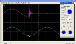
Today after reading your question I installed a measurement set up with my USB storage oscilloscope (which always has a little bit fuzzy traces, sorry for that) and catched the behavior during load step and load dump at 600W into 2R.
In order to show worst case I catched events close to the max of the sine wave.
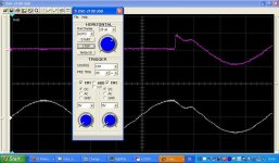
The first screen shot shows load step from zero to 600W.
The second screen shot shows the load dump from 600W to no load.
The probes were 10:1, means the voltage magnitude at load step and dump was 50V.
The upper trace is showing the voltage across the load, while the lower trace is showing the output voltage of the load.
Load step:
The sudden load pulls down the amp output a moderate portion, it takes about 15us to catch up completely and reach error free output again. No ringing.
Load dump:
The suddenly unloaded output causes a small overshoot, then the amp regulates back and after 18us it reaches error free output again.
No ringing at the amp output.
(But of course ringing at the suddenly opened load, which deenergizes according the parasitic RLC of the load and clamping of the switch itself.)
Overall, I would rate this as a very calm and stable behavior.
first trials with load step and load dump did not show any visible effect on the scope during continuous mode.
Today after reading your question I installed a measurement set up with my USB storage oscilloscope (which always has a little bit fuzzy traces, sorry for that) and catched the behavior during load step and load dump at 600W into 2R.
In order to show worst case I catched events close to the max of the sine wave.
The first screen shot shows load step from zero to 600W.
The second screen shot shows the load dump from 600W to no load.
The probes were 10:1, means the voltage magnitude at load step and dump was 50V.
The upper trace is showing the voltage across the load, while the lower trace is showing the output voltage of the load.
Load step:
The sudden load pulls down the amp output a moderate portion, it takes about 15us to catch up completely and reach error free output again. No ringing.
Load dump:
The suddenly unloaded output causes a small overshoot, then the amp regulates back and after 18us it reaches error free output again.
No ringing at the amp output.
(But of course ringing at the suddenly opened load, which deenergizes according the parasitic RLC of the load and clamping of the switch itself.)
Overall, I would rate this as a very calm and stable behavior.
Attachments
Last edited:
Very stable behavior Choco.....!!!!
I have seen amps breaking into excessive ringing with such tests, yours is really a robust amp with proper feedback loop which has excellent control over it.The voltage at output is stable with little ringing and maintains itself without any trouble.
Cheers
Kanwar
I have seen amps breaking into excessive ringing with such tests, yours is really a robust amp with proper feedback loop which has excellent control over it.The voltage at output is stable with little ringing and maintains itself without any trouble.
Cheers
Kanwar
...this topic also took its time during theoretic design and simulation and
of course I am pretty happy that my amp has read the same books as I did.
But this topic is even more complicated than you can find in linear control theory.
Real life amps a have massive non linear limitation: Rail voltage. Even if the control loop knows that it would need to feed the filter with a voltage beyond the rails - the MosFets cannot deliver this towards the filter, but are limited to the rails. I am calling this pre filter clipping.
This nonlinearity in the transfer function is adding a further burden to the control loop and can also become visible, when you are chasing an amp to reproduce large rectangular signals. In worst case it can happen that everything is looking fine at small levels , but at high levels the same amp could fall into an oscillation that remains even when the input signal is removed...
Some of my earlier simulation were trimmed to much higher loop gains, but there the necessary curings, like nonlinear dv/dt limitation of the input signal, became necessary to handle difficult signals or load situations.
My audiosotheric mind setting tells me that such pills are most likely not improving the sound and I decided to go for a control loop with moderate loop gain, which can handle all situations by its fundamental nature.
Further difficulties can be caused by integrating portions during clipping, if you do not stop or limit the integrator at clipping levels.
Fortunately these effects can be simulated very good.
In order to reduce simulation time I am doing a good portion of the control loop design with an averaged model which includes the complex gains and clipping limits of all amplifier stages.
Damping factor
Today I measured the damping factor, especially in the frequency range between 200Hz and 10kHz it touched the limits of accuracy of my measurement set up which was done by comparing the output voltage unloaded vs. driving a 0.047R load.
Related to an 8R load I am getting the following damping factors:
20Hz: 1400
200Hz: about 3000
2kHz: about 3000
10kHz: about 3000
15khz: 750
20kHz: 300
It appears like the decrease at low frequencies is caused by the growing
low frequency modulation on the rails and it should be possible to avoid that by using a regulated supply.
The decrease towards high frequencies is caused by the fundamental nature of the traditional L-C output filter. At its resonance frequency such a filter is acting towards the load like a current source.
With the chosen resonance frequency of 30.9kHz the increase of impedance becomes visible above 10kHz - of course mildened by the feedback...
Over Current Protection
I have to admit - the IRS20957S is a beauty.
It offers the level shifters, dead time adjustment, medium driving capabilities and shut down functionalities.
The over current protection can be set for the upper and lower MosFets independently. Furtheron uses the increase of Rdson towards higher temperatures to achieve an increased sensitivity at high temperatures.
I designed to theoretically identically shut down levels of upper and lower MosFet.
At Tj=25C it would theoretically act at 81A.
At Tj=150C it would theoretically act at 31A.
During the test on my work bench the heat sink was around 45°C (I cannot measure the junctions...) and the shut down was acting at 38A for the low side MosFet and 45A for the high side MosFet.
I configured the IRS20957S to auto reset and during continuous overload situation the amp retries operation in a hick up mode. As soon as the overload is removed the amp automatically provides normal operation again.
Of course it would be even better to design a fast (i.e. cycle by cycle) current limiter which folds back the modulation of the PWM exactly to the required level, and completely avoid shut down...
But I am satisfied with the auto reset and appreciate the simple circuitry with the IRS20957S.
...this topic also took its time during theoretic design and simulation and
of course I am pretty happy that my amp has read the same books as I did.
But this topic is even more complicated than you can find in linear control theory.
Real life amps a have massive non linear limitation: Rail voltage. Even if the control loop knows that it would need to feed the filter with a voltage beyond the rails - the MosFets cannot deliver this towards the filter, but are limited to the rails. I am calling this pre filter clipping.
This nonlinearity in the transfer function is adding a further burden to the control loop and can also become visible, when you are chasing an amp to reproduce large rectangular signals. In worst case it can happen that everything is looking fine at small levels , but at high levels the same amp could fall into an oscillation that remains even when the input signal is removed...
Some of my earlier simulation were trimmed to much higher loop gains, but there the necessary curings, like nonlinear dv/dt limitation of the input signal, became necessary to handle difficult signals or load situations.
My audiosotheric mind setting tells me that such pills are most likely not improving the sound and I decided to go for a control loop with moderate loop gain, which can handle all situations by its fundamental nature.
Further difficulties can be caused by integrating portions during clipping, if you do not stop or limit the integrator at clipping levels.
Fortunately these effects can be simulated very good.
In order to reduce simulation time I am doing a good portion of the control loop design with an averaged model which includes the complex gains and clipping limits of all amplifier stages.
Hi
This generally agrees with my findings, also I believe this is what mr. Putzeys was trying (not) to say about his new modulator.
That is: control loop such as yours is conditionally stable, under normal conditions the fast stabilizing action (>60kHz) will not allow the slower 30kHz instability to take over.
Until something really bad happens.
When it does happen it is even possible, that the loop will lock to the wrong mode, which is instability at where the phase crosses the magical point the first time. Just then the solution is to detect something went wrong and modify the loop gain to unconditionally stable to let it go back into stability mode.
Could you please elaborate on the stability criterion you've found in your book? Shame on me, I hardly speak Goethe's tongue on technical level.
I guess Bruno is running at much higher loop gains and higher order systems - in the range that I decided to avoid, because I doubt that I could handle the necessary 'pills' in an audiophile way. I am afraid, I cannot surpass Bruno and his R&D team just by some hours of hobby activity...
I found the stable configuration during transient analysis and then wanted to recheck in the bode diagram - and was wondering exactly like you how this thing can be stable and did not find a fit to the theory which I was aware of.
Months later in a pub with some beer I highlighted this strange thing to a friend and he remembered the book from J. Lunze.
Without that I would not have any literature on this topic at all and today I searched again for some english papers on this, but found nothing!!!
The book from J. Lunze is also just rushing across this criteria, with limited explanations. The condition that it is sufficient to have a positive phase margin just at the relevant frequency, where the gain crosses 0db, seems to be that the open chain has to be stable.
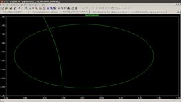
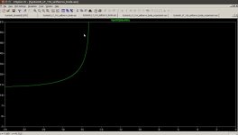
The bode plot and normal thinking model are misleading in this particular case. When watching the Niquist plot the often used criteria for stability that the graph shall not clasp -1 is fullfilled.
Here I have to thank a friend.Could you please elaborate on the stability criterion you've found in your book? Shame on me, I hardly speak Goethe's tongue on technical level.
I found the stable configuration during transient analysis and then wanted to recheck in the bode diagram - and was wondering exactly like you how this thing can be stable and did not find a fit to the theory which I was aware of.
Months later in a pub with some beer I highlighted this strange thing to a friend and he remembered the book from J. Lunze.
Without that I would not have any literature on this topic at all and today I searched again for some english papers on this, but found nothing!!!
The book from J. Lunze is also just rushing across this criteria, with limited explanations. The condition that it is sufficient to have a positive phase margin just at the relevant frequency, where the gain crosses 0db, seems to be that the open chain has to be stable.
The bode plot and normal thinking model are misleading in this particular case. When watching the Niquist plot the often used criteria for stability that the graph shall not clasp -1 is fullfilled.
Here the Niquist plot of the situation without load and without zobel.
You have to zoom, in order to see the relevant area.
So attached the first screen shot is from 0.01Hz to 1MHz and then two more detailed zooms towards higher frequencies.
Edit: Note that the last zoom does not show the highest frequency, but detail zoom around -1.
You have to zoom, in order to see the relevant area.
So attached the first screen shot is from 0.01Hz to 1MHz and then two more detailed zooms towards higher frequencies.
Edit: Note that the last zoom does not show the highest frequency, but detail zoom around -1.
Attachments

Last edited:
Hi Markus,
did you have a chance to look on Classical Feedback Control with MATLAB, Boris J. Lurie and Paul J. Enright, Marcel Dekker, NY, 2000 and Feedback maximization, Boris J. Lurie, Artech House, 1986?
did you have a chance to look on Classical Feedback Control with MATLAB, Boris J. Lurie and Paul J. Enright, Marcel Dekker, NY, 2000 and Feedback maximization, Boris J. Lurie, Artech House, 1986?
"The condition The condition that it is sufficient to have a positive phase margin just at the relevant frequency, where the gain crosses 0db, seems to be that the open chain has to be stable."
I find this delicate detailed thing very interesting since I am working on increased loop gain for my simulations, but still: What exactly is a "stable open chain"? Choco, if you don t find the right words/expressions, may you explain it in german to me? Many thanks! From my understanding, phase 180° where gain >0dB means uncontrolled (ever increasing) oscillation.
I find this delicate detailed thing very interesting since I am working on increased loop gain for my simulations, but still: What exactly is a "stable open chain"? Choco, if you don t find the right words/expressions, may you explain it in german to me? Many thanks! From my understanding, phase 180° where gain >0dB means uncontrolled (ever increasing) oscillation.
@Dimitri,
I have not read the books you mention. Do they particular elaborate on the topic, which we are discussing (if yes, please point to the chapter) - or are they simply books on control theory that you recommend?
Unfortunately control theory does not care about human brains.
Stable open chain means to me that the open chain does not oscillate.
I found a link which let's you look into the book from Lunze. Unfortunately it is another revision than what I have and they also restrict the pages you are allowed to see. Page 405 example 8.9, bode diagram on page 406.
Regelungstechnik 1: Systemtheoretische Grundlagen, Analyse Und Entwurf ... - Jan Lunze - Google Books
I have not read the books you mention. Do they particular elaborate on the topic, which we are discussing (if yes, please point to the chapter) - or are they simply books on control theory that you recommend?
That's what I call healthy human thinking.From my understanding, phase 180° where gain >0dB means uncontrolled (ever increasing) oscillation.
Unfortunately control theory does not care about human brains.
Stable open chain means to me that the open chain does not oscillate.
I found a link which let's you look into the book from Lunze. Unfortunately it is another revision than what I have and they also restrict the pages you are allowed to see. Page 405 example 8.9, bode diagram on page 406.
Regelungstechnik 1: Systemtheoretische Grundlagen, Analyse Und Entwurf ... - Jan Lunze - Google Books
Hi Markus, can you please explain how you did this?I found the stable configuration during transient analysis
...horse sense tells that it is helpful to put a D portion in the loop, in order to handle the ugly class D output filters - a structure like in posting #3 is a natural starting point and no contradiction to human thinking.
That was 20 years ago, when I played the first time on a buck converter...
Edit: And at that time already my prof told me that a D portion is fine from point of control theory, but ugly in terms of noise in real switching systems, and he also told that it would be common practise to measure the current in the inductor or the cap in order to get an equivalent information for the control loop.
Picked up this starting point again. ..experimented with different gain, with additionally integrating gain etc... and soon came to a PID loop that was rock stable with nice step response, but showed a bode plot as discussed.
That was 3 years ago.
The shaping clue, which is about 14 months old, doesn't bring a fundamental change to the control loop.
Last edited:
- Home
- Amplifiers
- Class D
- System_D_MD, Class D is like chocolate