X, the position of the camera is distorting the view. Tho a little fill does look to be needed. Tricky precision is an absolute requirement to get this right. 🙂
Last edited:
the position of the camera is distorting the view
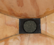
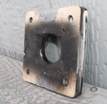
I see the barrel distortion in the bowed horn rim, but the CD throat looks round and the wood throat looks rectangular, maybe 1.2:1 aspect ratio. It is a straight ahead view so perspective distortion should be minimal and barrel distortion is minimal on center-line.
Legis' Synergy throat was a compromise, he made the horn for a cone loudspeaker with about a 4" rectangular throat, then put a 2" exit driver on it, and later filleted in the gaps, still resulting in a throat that rapidly expands, then transitions to a conical expansion.Your CD throat looks to be non-square - was that by design? I seem to recall that Legis used a rectangular throat on his synergy and it may have caused some HF artifacts.
Gedde's Oblate Spheroid (OS) horn throat transitions to conical with no diffraction causing "bumps" in the path, Hughes Quadratic Throat is a simple approximation of the OS.
The OS or QT would be ideal for the Synergy throat, except the curvature makes the mid driver mounting problematic, and extends the horn length for a given pattern control frequency which is dependent on horn diameter.
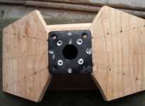
Your observation caused me "paralysis by analysis", I still have not finished the horn throat transition smoothing, which will also include smoothing in the horn itself, presently the transition is just roughed out on the 1/2" adapter driver mounting plate. Because of the accuracy and strength needed, I used 1/4" aluminum laminated to Baltic Birch for the adapter, reusing some 1.4" to 2" adapters made for a previous project. Six of those units are still available for anyone wanting to make their own SynTripP using 1.4" or 1.5" drivers.
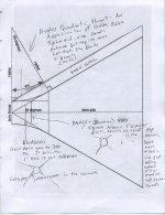
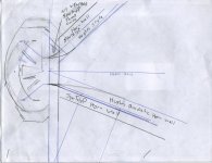
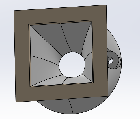
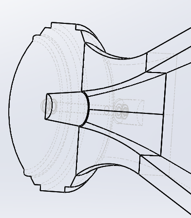
My SynTripP throat is a compromise between the OS and the usual ways of making the round to rectangular conversion. The pictures below outline some of the options and difficulties involved.
So no sound still, as there still is several hours finish work with multiple dry times between before mounting the driver, but the 10" drivers just arrived while typing this up. There probably will be no more progress until Monday, as we have company staying with us, and they don't share our speaker obsession 🙂.
Art
Attachments
Last edited:
Thanks for the explanation - I see what you are doing now. It looks good as you made the smooth transition using the BB ply piece. Nice closeup photos.
I seem to recall that Legis used a rectangular throat on his synergy and it may have caused some HF artifacts.
Yes they were rectangular at the beginning, around 5,5-6cm x 8,5-9cm (2.16-2.35" x 3.35-3.54") IIRC. Vertical transition is quite "tight" like with Art's throat, horizontal plane has more rapid expansion at the throat due to the geometry.
If you zoom this, you can see the throat without any goop with the 2" dia comp driver hole is there for reference: http://i817.photobucket.com/albums/zz95/LegisActio/Synergy%20Horn/Synergy5_zps788f6016.jpg
And with the goop work done: http://i817.photobucket.com/albums/zz95/LegisActio/Synergy Horn/redhorn2_zpsa3381d0b.jpg
Last edited:
Art- thanks for the images describing the horn expansion. I have been wondering if something neat could be done with the 3d printer- looks as though I have found it 🙂
At the very least, I will be printing a throat adapter
At the very least, I will be printing a throat adapter
At the very least, I will be printing a throat adapter
JG,
In that case go with the oblate spheroidal waveguide throat. This really is the most critical part of the horn and it's where your 3d print approach will yield something the average guy with conventional wood working tools won't be able to duplicate. You will need to do some research to get the profile. Rather than program that find a scale drawing and import the bitmap into your program. Then hand overlay a 2point spline over the profile and then do a 3d revolved profile along an axis.
It gets a little more complicated than that because you need to work towards the rectangular profile. There is a thread on here where member hulkss already made a transition similar to that to be 3D printed. This one followed the Hughes paper (see above comment by Art about the similarities to the OS shape):
http://www.diyaudio.com/forums/multi-way/88237-suitable-midrange-cone-bandpass-mid-unity-horn-97.html#post3524576
And more in depth:
http://www.diyaudio.com/forums/multi-way/88237-suitable-midrange-cone-bandpass-mid-unity-horn-99.html#post3529953
I played with the transition a bit in my favourite 3D tool and his approach (see his picture above) makes sense to me...
Last edited:
Wesayso,
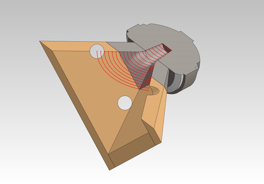
Thanks for the links - the theory and method in 3d cad for this been laid out for us by Hughes, and Hulkss, respectively. So in summary, generate a series of Hughes arcs tangent to the horn wall and CD throat exit over various azimuthal planes. Then use the lofting tool to generate the 3d shape in the azimuthal direction with the Hughes arcs. Very nice. It is this sort of "trick" that makes all the difference. Sort of like it took me a day to figure out how to generate a tractrix in 3d (easy) and to translate that arbitrary 3d curve to a flat template for easy cutting. I had to use the sheet metal lofting tool and then unroll it flat. It could not be unrolled unless it was a sheet metal lofting operation to form the 3d shape.
Thanks for the links - the theory and method in 3d cad for this been laid out for us by Hughes, and Hulkss, respectively. So in summary, generate a series of Hughes arcs tangent to the horn wall and CD throat exit over various azimuthal planes. Then use the lofting tool to generate the 3d shape in the azimuthal direction with the Hughes arcs. Very nice. It is this sort of "trick" that makes all the difference. Sort of like it took me a day to figure out how to generate a tractrix in 3d (easy) and to translate that arbitrary 3d curve to a flat template for easy cutting. I had to use the sheet metal lofting tool and then unroll it flat. It could not be unrolled unless it was a sheet metal lofting operation to form the 3d shape.
X,Thanks for the links - the theory and method in 3d cad for this been laid out for us by Hughes, and Hulkss, respectively. So in summary, generate a series of Hughes arcs tangent to the horn wall and CD throat exit over various azimuthal planes.
All well and good, but look at the diagram second from the right in post 143, notice the Hughes throat transition would require 1" thick horn walls for the SynTripP, a weight gain I am not willing to accept, though for home or fixed use, the Hughes transition would be nice. The extra horn wall thickness would require all the ports to be redesigned. It would also put the mid injection ports further from the HF driver entrance, which would degrade off axis polar response in the crossover region, another compromise I'm unwilling to accept. Other than that...
Broke in the 10" drivers laying on a towel face up using a 17.25v 20 Hz sine wave, which results in 12mm peak to peak cone travel. SPL read about 80 dBC near the drivers, loud enough to make me feel ill after just 5 minutes, makes me wonder about home theater guys going for 120dB at 20 Hz...
After 45 minutes, the magnet structures were hot to the touch, kitchen thermometer read 148F after sitting under the magnet structure for 5 minutes. Room temperature was 60F, 42 RH, water would evaporate off the magnet structure in a few seconds.
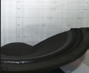
Next step is to photograph the cone at (or just below 😉 Xlim so I can figure the routing depth and ring diameter needed to provide clearance, and the filler cone profile. The new BC10CL51 drivers have a more curved cone shape than Jennygirl's profile shows.
Preliminary push tests show the outer surround and cone peak near the same distance forward, but the inner roll does not seem to go beyond the gasket depth, so the router ring can definitely be reduced from my previous estimate. Glad I waited for the actual cones before routing the relief ring, now it will be in the correct position for minimal wood removal and minimum ATC volume.
After routing can screw and glue the horn adapter plate on and finish smoothing the transition, and start testing frequency response of the horn prior to port holes.
Art
Weltersys,
The 3d model is 1 in thick because it was drawn that way not out if necessity. The 3d throat appears to be maybe 4 in deep from CD flange on out. In Jennygirl's build if she uses a 3d printer she could print the entire thing ports, braces, vents, mounting bosses, ribs, walls, honeycomb stiffeners, etc in one swoop out of molten ABS rod. I think your horn is 24 in wide - right at the limit.
Looks like you are pretty close to sound. Nice work on looking at max excursion on surround. I am guessing not much routing will be needed.
Yeah the surround is really beefy. It's hard to push past the gasket. That's why initially I said 7-8mm xlim, because I couldn't perceive that speaker even putting that amount of force on it 😉
That's weird it came out more curved. What about depth wise?
That's weird it came out more curved. What about depth wise?

Jennygirl,
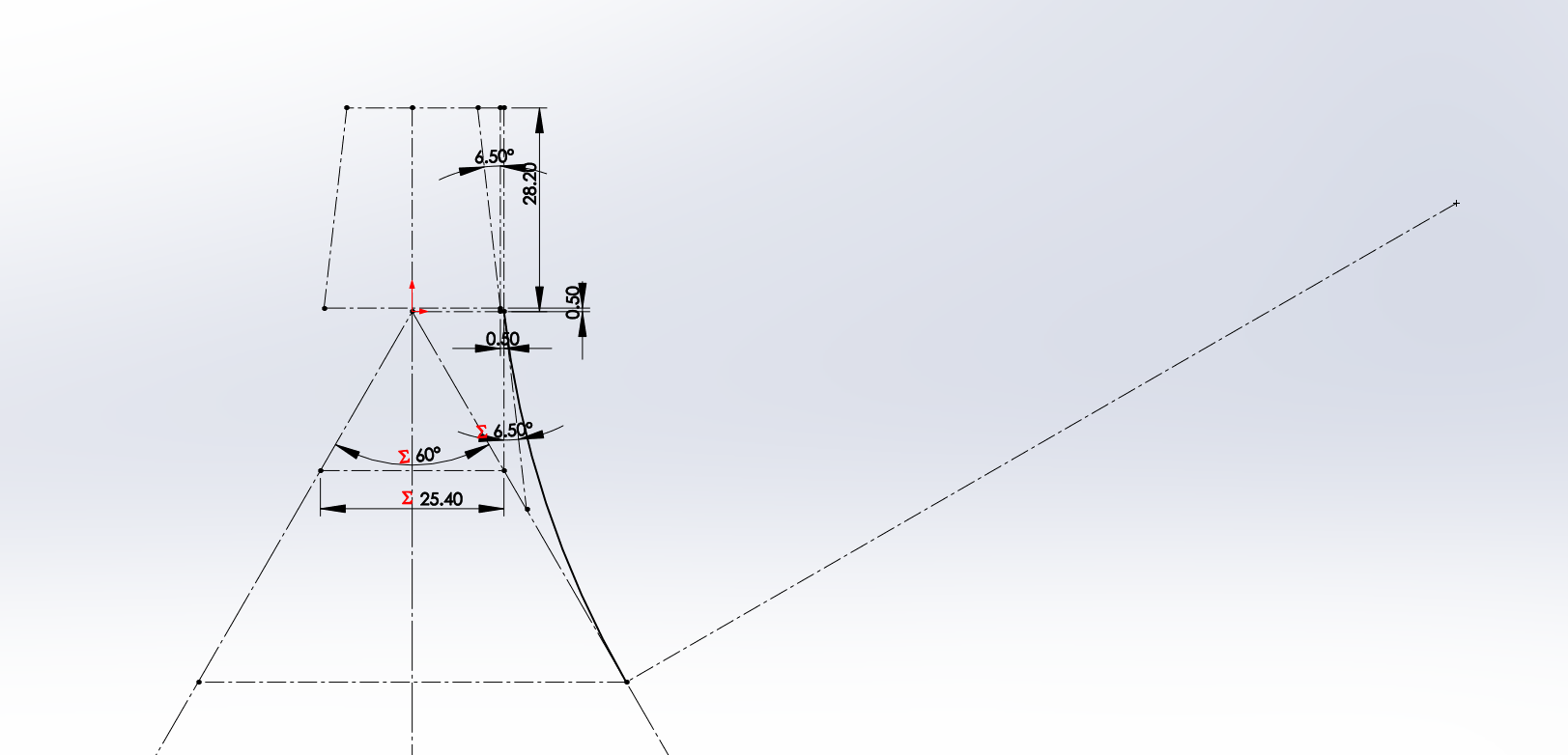
Hulkss states:
" I also matched the driver exit angle of 7 degrees and located the horn apex 10 mm into the driver throat to get the driver closer to the midrange ports."
That is similar to what I have done with the SynTripP throat entrance, though the Celestion driver exit is 0 degrees. However, by moving the horn apex into the driver throat the transition is no longer the Hughes approximation of the Geddes OS coordinate system.
It will be interesting to see what set of infinite points you decide to choose in the transition between round and rectangle with two different angles.
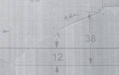
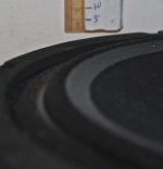
Your BC 10CL51 drawing nearly perfectly matches the cone profile, other than the area near the cone edge continues the arc, probably less than a maximum of 1mm deviation over a 30mm section shown in the photo below detailing the slightly different arc area.
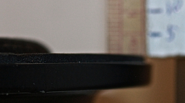
The BC 10CL51 excursion at 15 volts 60 Hz (open air) is equal to the speaker gasket height, the inner roll being the first to go beyond, at 45v the cone surround extends another 4 mm past the gasket, the apex being at the surround/cone glue joint. Xlim is 10 or 11mm, peak to peak travel of 20mm was measured, I estimate another 2mm is possible but did not subject the driver to more than 45v to confirm that, as it probably would be a "one time only" event letting out the magic smoke. Repeated attempts to photograph the cone excursion under power failed to produce decent results, the photos below show excursion pushed "by hand", pushing up as close to the voice coil as my fingers could fit.
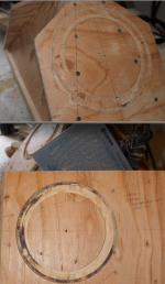
I had planned on routing a 5mm deep x 33mm wide channel to accommodate peak excursion, requiring four passes with a 1/4" bit, but unfortunately the router depth adjustment spun, resulting in a 6mm depth on the inner and outer channels. After noticing the "silly millimeter" adjusted the router depth back to 5mm for the middle channels. To duplicate the ATC used in my SynTripP, one could set router depth to 5.5mm 😉.
Back to the shop to finish up the throat, hope it is not as windy as yesterday, or outdoor tests may have to wait.
Art
Attachments

Last edited:
I'm looking forward to seeing/hearing the results Art! I may be thinking a few steps ahead, but for the second stage of the horn (the 'flare'), what's the best way to assemble and attach it to the first stage?
Getting the compound angles for the joining edges isn't that difficult, but what's been difficult for me has been to get the joining edges to line up...
Edit: Ah, I see in your diagram a few pages ago that you'll have the 'mouth' fit over the rest of the horn. I'm intrigued to see how you do it, because I've drawn a serious mental blank with this 🙂
Great detailed study of the max excursion limit on the 10CL51. Thanks for that - will be of great use for folks following you on this build. Amazing you can apply 45v to it without it complaining. That is above the rms thermal limit. Looking forward to seeing he cones bolted down. Did you do the HF measurements yet as they need to happen before the ports are cutout.
X,Amazing you can apply 45v to it without it complaining. That is above the rms thermal limit. Looking forward to seeing he cones bolted down. Did you do the HF measurements yet as they need to happen before the ports are cutout.
It complained, but I wasn't listening😉. For sine wave voltage that high, the tests must be short, even though the open air impedance at the 60Hz Fs is somewhere in the 40+ ohm range.
Still not done with the HF horn adapter, spent the morning trying to determine availability of a second 16 ohm CDX14-3050, but I'm going back to the shop again now.
Art
Eight hours later finally have the box completed and primer drying ready for final sanding of the throat.
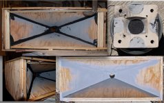
The grill frame splits the difference in angles between the first horn section and the second detachable section, reducing diffraction effects, and reducing mid-range "waistbanding" in the pattern when used without the second horn section.
I quit before cutting the angles on the top and bottom grills, as one only gets one chance to get the angle and length correct, and after 12 hours at it figured I'd have a better chance getting it right tomorrow- half my build time seems to be correcting mistakes 🙄.
Tests will commence manana, after siesta time ..
Art
Attachments
Wesayso,
Thanks for the links - the theory and method in 3d cad for this been laid out for us by Hughes, and Hulkss, respectively. So in summary, generate a series of Hughes arcs tangent to the horn wall and CD throat exit over various azimuthal planes. Then use the lofting tool to generate the 3d shape in the azimuthal direction with the Hughes arcs. Very nice. It is this sort of "trick" that makes all the difference. Sort of like it took me a day to figure out how to generate a tractrix in 3d (easy) and to translate that arbitrary 3d curve to a flat template for easy cutting. I had to use the sheet metal lofting tool and then unroll it flat. It could not be unrolled unless it was a sheet metal lofting operation to form the 3d shape.
Since we're on the topic, I attempted to make a Hughes adapter, but used a slightly different method, posted in the same thread as hulkss variant. http://www.diyaudio.com/forums/mult...-bandpass-mid-unity-horn-134.html#post3671552
Perhaps it's possible to get a second opinion on whether it seems sound (the method was very simple at least) and it might even be useful to this thread.
Cookiemonster,Perhaps it's possible to get a second opinion on whether it seems sound (the method was very simple at least) and it might even be useful to this thread.
The Hughes Quadratic throat is "sound", but in terms of usefulness for a horn using a HF driver and offset mid drivers, not very, as it's shape requires moving the mid driver entrance further from the HF driver entrance, which then requires delay correction to bring the drivers into alignment.
Art
- Status
- Not open for further replies.
- Home
- Loudspeakers
- Multi-Way
- Synergy Tripp 10"