
As you may have realized, the inactive transistor of the output stage keeps his quiescent current during the half wave of the active transistor. In usual AB amplifiers the quiescent current of the inactive transistor goes to zero as soon as the active transistor crosses is conducting with more than its quiescent current.
The nodes of Q1-Q4-Q5 and Q6-Q8-Q10 are not properly defined for use in the real world.Q5 and Q10 will run away. This configuration is other then the simulation not stable.
Current mirrors Q4-Q3 and Q8-Q9 are not properly defined for use in the real world unless both mirror-Q's are on the same die. Add small (100E) resistors in the emitters of all mirror-Q's.
Diodes D1 -- D4 can be omitted.
Current mirrors Q4-Q3 and Q8-Q9 are not properly defined for use in the real world unless both mirror-Q's are on the same die. Add small (100E) resistors in the emitters of all mirror-Q's.
Diodes D1 -- D4 can be omitted.
Are D1/2/3/4 meant to set the bias? They would be mounted alongside the output darlingtons on the heatsink?
The 1% distortion is because your driving right into clipping. Try driving it not into clipping?
The 1% distortion is because your driving right into clipping. Try driving it not into clipping?
When one output transistor conducts a large current, on the other side, Q4 or Q8 saturates and the voltage across D1-D2 or D3-D4 plus the saturation voltage minus the output transistor's VBE divided by the value of R4 or R5 defines the remaining current.
I think D1...D4 also set a minimum to the quiescent current, but no maximum. It would definitely be interesting to see what a bit of mismatch between the mirror transistors would do.
I think D1...D4 also set a minimum to the quiescent current, but no maximum. It would definitely be interesting to see what a bit of mismatch between the mirror transistors would do.
Q5 and Q10 will run beserk anyhow, so the rest is academic.
Start modeling the bjt's according to specs and no output anymore.
Start modeling the bjt's according to specs and no output anymore.
Deliberately causing some unbalance with resistors between the bases and emitters of the output transistors could solve that, but then Q4 and Q8 already saturate in the bias point. Maybe the built-in base-emitter resistors of the output Darlington transistors already do the trick.
The base of both Q5 and Q10 are not defined: between two collectors.
Hence no Vbe definition of Q5/Q10. They run beserk.
Output is either V+ or V-. Could become a full short too.
It is not an audio amplifier.
Hence no Vbe definition of Q5/Q10. They run beserk.
Output is either V+ or V-. Could become a full short too.
It is not an audio amplifier.
That's also what I thought at first sight, but when you look up the datasheets of Q5 and Q10, you will see that they are Darlingtons with built-in resistors between base and emitter, also in their first stage. Hence, when the differential pair and current mirror are sufficiently well-balanced (for example by selecting parts), the resistors pull up the base of Q5 until Q4 starts to saturate and pull down the base of Q10 until Q8 start to saturate. That will give you a sort of defined bias point, but probably also lots of distortion.
...but probably also lots of distortion.
It could work as a square wave generator.
If the simulation works, the amp MAY work in reality.
If the simulation fails, the amp FAILS definitely.
If the simulation fails, the amp FAILS definitely.
Give me please the spice models of TIP120/125 you use. I will try to resolve the problems .
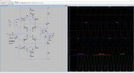
Thank you very much. I have attached the requested files and the LTSpice model. The diodes are intended to set the bias point of the output transistors together with their emitter resisitors.
Thank you very much. I have attached the requested files and the LTSpice model. The diodes are intended to set the bias point of the output transistors together with their emitter resisitors.
Attachments
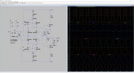
I made a simple model without current mirrors to start with . Biased 150ma with 0 ohm input source impedance 8 ohms load to expect 25 decent watts . The first results are spectacular. Dtot=0.14% at 5w to 20w 1% at 25w . The blindness is 50ns too high to reproduce the most difficult requiem of Mozart (20ns) but sufficient to reproduce the pleasant beat of horns in large jazz orchestras, as sing sing sing of B. Goodman's. Very promising. Thermal stability is a difficult issue here.
Attachments
Thank you very much. I have attached the requested files and the LTSpice model. The diodes are intended to set the bias point of the output transistors together with their emitter resisitors.
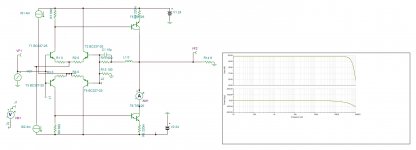
I have modified the circuit design a little bit according to your hints:
- matching resistors in the emitter line of current mirror and differential amp
- reduction of the emitter resistors of the output stage
So, in this way it should work better for unmatched transistors.
Attachments
Perhaps you should explain this 20 nanosecond thing for Mozart's requiem, given that the audio bandwidth is 20kHz and can be reproduced accurately from samples spaced 20µs apart, one thousand times as long.
- Status
- Not open for further replies.
- Home
- Amplifiers
- Solid State
- symmetric audio amplifier