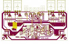
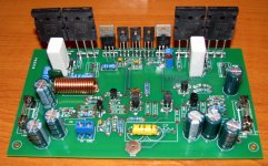
I will definitely set correct bias current after finalizing a stereo build, 😉 I was actually surprised to get a low DC offset, I have never measured to match the input diff trannies. The bias trimmer reads 1.4k ohms before soldering it in place, and after about 2hrs of playtime the heatsink is getting warmer. It looks normal to me. Hope I will be able to squeeze my hobby time and finalize my build coz' I'm currently doing fixes and improvement of my kitchens place (the missus wanted me to prioritize the task hehe 😀). Anyway I will be sharing the files in case anyone wanted to get their hands on my pcb lay-out (toner-transfer for home etching) 😉
BTW In the parts placement guide, small signal trannies are MPSA ( !As is for the input diff trannie - 2SA970BL! ) In my actual build I have used 2Ns. WARNING! 0bserve pin terminal designation.
Thank You!
BTW In the parts placement guide, small signal trannies are MPSA ( !As is for the input diff trannie - 2SA970BL! ) In my actual build I have used 2Ns. WARNING! 0bserve pin terminal designation.
Thank You!
Attachments
SYMEF and the other designs of OnAudio's are all geared towards +/-40V rails with, IIRC, +/-50V being the recommended maximum.
Sounds about right, 2x 30Vac after losses gives an nice ~+/-40Vdc supply, up to 2x 36Vac for a set of ~+/- 50Vdc rails.
Not so good,fired up one channel with a light bulb tester stays bright light;Fired up without tester C15 gone in smoke blew up
I have an un-stuffed set of the 'Drowranger' v1 boards, which are somewhat different than yours. I was initially sent the v2 boards so that is what I built.
C15 is just a little rail decoupling. From your pic I think the polarity was OK. The only things I can think of that would pop C15 would be applied voltage polarity was wrong, a really significant oscillation that heated the capacitor via its ESR / ripple current being exceeded or uncontrolled quiescent current, again resulting in heating if the capacitor.
Are you able to run it on a properly limited supply and check for oscillations and verify the bias circuit is functional?
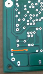
With the bulb tester the current was limited but the bulb stayed lit so there was something wrong but what?I checked everything for right polairity like caps and diodes.What can cause the current draw?The pic isn't my board it is only to let you know what version I have
Must the trimpot set at high resistant before starting up?
I use a 2x30Vac transformer and C15 is a 100V type
I use a 2x30Vac transformer and C15 is a 100V type
Found the mistake my own fault the drivers Q2 and Q16 weren't insolated from the heatsink forget to use the nylon bushing
Oh that's good news!Found the mistake my own fault the drivers Q2 and Q16 weren't insolated from the heatsink forget to use the nylon bushing
Waiting for listening test.
I have a pair of unpopulated boards
Thimios.
I wold think there's lots for latitude in the choice of capacitor. Anything from 22µF to 100µF should be fine. It is just decoupling, so it isn't critical as far as actual value is concerned.
I replaced the output trannie use the light bulb tester so far so good.Setting the bias slowly reach 23mV then C 3 begins to smoke
The decoupling in the same location on the other side? Have they been built to OnAudio's BOM, or are there ant substitutions at all?
So, it behaves OK until you get up to the desired bias point by the sound of it. Still smacks of oscillation. I would try relocating the 39pF compensation caps that currently go from VAS collectors to ground to VAS collectors to their respective bases. In other words trade the shunt compensation for Miller compensation. Connect C5 across Q4's B-C junction and C12 across Q15's B-C junction.
So, it behaves OK until you get up to the desired bias point by the sound of it. Still smacks of oscillation. I would try relocating the 39pF compensation caps that currently go from VAS collectors to ground to VAS collectors to their respective bases. In other words trade the shunt compensation for Miller compensation. Connect C5 across Q4's B-C junction and C12 across Q15's B-C junction.
- Home
- Amplifiers
- Solid State
- SYMEF amplifier