ostripper said:Gave them PCB's to Danielwritesback
 That's, why he became so silent.
By Forr - My concern is that current flows through C8 because of the varying voltage at Q5 collector, but Q6 collector voltage being almost fixed at about +0.6 V above ground, current variations in C7 can only be very small. So I don't think we can consider that C7 and C8 load the LTP collectors equally.
You are correct , in the sim there is only a couple uA on C7 (green)
100's on C8 (red). I guess C7 can go , I'll try it. It does not seem to add another pole to the amp. If you replace the cascode with a resistor (22k) , it does.
I will have check whether removing C7 has any effect on THD, FFT , and loopgain response.
OS
Attachments
Hi Ostripper,
In fact, Q6 replaces a resistor in parallel with a capacitor of an initial design that was first published by Hitachi, I think. So at high frequencies, with this older scheme, C7 will continue to see almost no voltage variations, because alternatively coupled to the collector-base node of Q7.
The purpopse of common base Q6 or the old RC network is to maintain DC voltages at collectors of Q4 and Q5 roughly equal, getting the same thermal dissipation for them.
Member
Joined 2009
Paid Member
OS,
The pcb explanation makes good sense now, I hadn't understood how you were doing it properly before.
The other question I had was bass 'slam' - is this just down to having a big caps on the input and feedback loop or is there more to it than that ?
The pcb explanation makes good sense now, I hadn't understood how you were doing it properly before.
The other question I had was bass 'slam' - is this just down to having a big caps on the input and feedback loop or is there more to it than that ?
By bigun - The other question I had was bass 'slam' - is this just down to having a big caps on the input and feedback loop or is there more to it than that ?
Some , like mike chua of ampslab , say the metal can(TO-3) devices give better bass , others say it is the topology. They are both right,
as the ability of the OPS to handle transients is the key. Then , your assumption is also right , having more current and voltage does have a MAJOR impact. The 2 OP supersym's I gave to DWB did not have the "slam" that the new 4 pair boards do on the same PS. Conversely,when the 2 op pair boards were run on an 300VA EI, the bass was normal(not impressive). With the 1500VA and 100's of K uF , ULTIMATE scary bass.
So , with each improvement (2 to 4 pair , 300Va to 1500VA) a very noticeable bass improvement occurred. With the 2 pair OPS , I think
beta "droop" at high level , hard loads affected bass response.
OS
Hi Gareth,
You are really talking about the ability of a circuit to deliver high currents accurately. The ability of an amplifier to control a bass driver.
I think most well designed amplifiers can do this easily. Most of these will be solid state and be of a higher power. That way you don't run into protection circuits limiting the current, or a loss of gain in the output stage that allows the current output to drop.
Being a subjective thing using a wide variety of speakers and cables, this is really not a valuable term. There is no real definition and really only points to amplifiers that have limited power or current output.
In short, nothing to worry about.
-Chris
ostripper said:I have only gotten this far on the PCB , I whether a am wondering whether a 3 X 9" with opposed output pairs would be a better
design instead of "the long way" (Attached).
OS
My 2-bits for the PCB layout: I much prefer a long layout with single row of output devices when the amp is this powerful. It better suits the most common long-sided heatsink/chassis configuration, and leaves ample room in the center of the chassis for the power supply.
..Todd
My 2-bits for the PCB layout: I much prefer a long layout with single row of output devices when the amp is this powerful. It better suits the most common long-sided heatsink/chassis configuration, and leaves ample room in the center of the chassis for the power supply.
That is what I propose , with the single row OPS like I have on a 3.5" X 9", mounting flat on a 5" heatsink will look real cool , leaving that room for psycho power supplies
 That is what I think we all want , the most universal layout.
The only reason mine is 5.5" X 8" is I made it for the stealth amp.
OS
ostripper said:
That is what I propose , with the single row OPS like I have on a 3.5" X 9", mounting flat on a 5" heatsink will look real cool , leaving that room for psycho power supplies
The only reason mine is 5.5" X 8" is I made it for the stealth amp.
OS
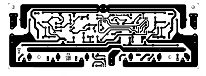
Yup. Perfect. In fact, it ain't too different from my DX HRII-55 layout. (Based loosely on Quasi's layouts.)
..Todd
Attachments
Hi Todd,
Anything except a "Proximity" would make a nice 4B retrofit.
To be honest, rebuilding a 4B with better quality parts, matched where required, might solve the sound quality issues. A redesigned bias circuit and modified setup procedure would solve the reliability and temperature issues (as well as cold start sound quality). An inrush current limiting circuit, coupled with an output protection circuit would remove my last objections for using this amplifier. Finally, beefing up the chassis at the bottom of the front face plate would prevent it from ripping free unexpectedly.
Hey! We now have a normal amplifier!
I'm not sure, but I think they call that an "SST" 😉 , although I haven't actually looked at one. Does that have a protection network?
-Chris 😀
By taj - Yup. Perfect. In fact, it ain't too different from my DX HRII-55 layout. (Based loosely on Quasi's layouts.)
Do you think I should include the fuses ? The larger rail caps I intend to use take up a bit of space. Smaller fuses , like 20mm ones (3/4")
would be doable.
OS
You're probably right, Chris, but as DIY'er I much prefer gutting them and using a DIY design (I did that with my house too). Of course you still have to deal with the protection and in-rush concerns. (Do you really need to be concerned about in-rush with a pair of 500VA EI transformers?)
At any rate, OS's version of the Symasym circuit suits the rail voltage and the number of output devices perfectly, so using this to retrofit the Bryston would be relatively easy in terms of physical fit.
..Todd
At any rate, OS's version of the Symasym circuit suits the rail voltage and the number of output devices perfectly, so using this to retrofit the Bryston would be relatively easy in terms of physical fit.
..Todd
OS, I think you should include the fuses if you can, but the earth will continue spinning if you don't. The 5x20 mm forms are indeed easier to fit.
..Todd
..Todd
ostripper said:
Do you think I should include the fuses ? The larger rail caps I intend to use take up a bit of space. Smaller fuses , like 20mm ones (3/4")
would be doable.
OS
Hi ostripper,
If board space is limited, the pico fuse II is available in values up to 10A and 125V rating. These are only 8mm long.
By steve dunlap - the pico fuse II
Those are cool.. 😎
An externally hosted image should be here but it was not working when we last tested it.
I will keep them in mind for my small amps (BTF50) or auxiliary supplies. What I want is something very "findable" (scrap heap , mouser , digikey , chinese 😀 ) , and replaceable.
OK , with the general circuit I have posted , these are the possibilities and limits of modification.
1. Addition of a used defined Cascode with the option of a BJT or JFET differential. For this I will research the device package literature to get a good layout with face to face coupling (thermal) and maximum flexibility.
2. Like on my present one, a "one piece" VAS with just a small 30mm X 100mm (1 X 3.5") flat heatsink.
An externally hosted image should be here but it was not working when we last tested it.
3. Big FAT 6800 - 10K on board main rail capacitance(C16/17 , 470u secondary LTP/VAS decoupling. (C12/13)
4.OPS - make layout so 2sc5200/2sa1943 , MJL/NJW 0281/0302 , or EVEN IRF 240/9240 (I know you wont mind , chris !! ) are usable. The IRF's would just require a few extra pads for the gate protection and a different Vbe coefficient,and higher resistance gatestoppers.. (no real layout changes).
5. A few added pads for user defined compensation preferences.
I did use the exact R/C shunt compensation at the VAS , just Cdom at C7, and the 22pF lead comp. of the original symasym and the open loop response and phase margin was within 2% of my compensation scheme. 😎
any other suggestions are welcome .. I'm on it...
OS
Attachments
Try to compensate Miller of amp Matti Otala, (better simulation I had)
http://peufeu.free.fr/audio/schemas/Matti Otala.pdf
Distortion in HF must improve, Slew-rate must increase
http://peufeu.free.fr/audio/schemas/Matti Otala.pdf
Distortion in HF must improve, Slew-rate must increase
R26-R27? Ughh I absolutely dislike this type of compensation. Oh, well... But the staggering high amount of it, 2k2 only? It's little over applied, isn't it? 
Is this a genuine Matti Otala design?
Why are the resistors quantified with mF or nF?
Is this a genuine Matti Otala design?
Why are the resistors quantified with mF or nF?
- Home
- Amplifiers
- Solid State
- Symasym - the next generation (supersym)