Now we know. Even I was interested but then the thread halted ...
Thanks Roender to let us know your impressions of the design.
Gajanan Phadte
Thanks Roender to let us know your impressions of the design.
Gajanan Phadte
i am very very interested - please put this name in Your thread when You open it......
it is expected with great couriosity 🙂
😀
it is expected with great couriosity 🙂
😀
Triodas said:Keep us in loop Roender, please.
sunrise said:i am very very interested - please put this name in Your thread when You open it......
it is expected with great couriosity 🙂
😀
http://www.diyaudio.com/forums/showthread.php?s=&threadid=111756
Hi Reonder,
Can you take a look the attached schematic. It similar to what you worked on couple years ago accept I added a Vbe multiplier like in MikeB's original design and I'm not using the same output transistors as you did but everything else is pretty close to the same.
I have two prototype boards built but I can't seem to bias the output transistors at all. I can get a sine wave through the amps into an 8 ohm load and it actually measures and look pretty good without any crossover distortion, but at DC with the inputs grounded i get 0V between R8 and R9. The current at R23 and R24 is approx. 2ma, and 11ma at R33, and about 5.5ma at R17 and R18. These current values seem right to me according to my simulations. I get a very low and unstable voltage across the Vbe multipltier that drifts around, and R36 does nothing when i adjust it. I tried increasing R35 to 2k and still no bias. I checked Q17 and it checks Ok and placed correctly.
Any ideas what could possibly be the problem.
Thanks,
Al
Attachments
Bias generator
hi Al,
Most probably the HFE of BD139 is not sufficient. Did you use the BD139/16?
I would suggest to use the 2SC3807 or 2SD809E/F.
I like the schematic !
best
hi Al,
Most probably the HFE of BD139 is not sufficient. Did you use the BD139/16?
I would suggest to use the 2SC3807 or 2SD809E/F.
I like the schematic !
best
Hi Andrew,
The voltage across C11 and R16 jumps all over the place. It even switches polarity at times, but typically less than 500mv. It appears the BD139 Q17 is not turning on eventhough I'm getting current through the VAS. I'm thinking the problem could lie in the cascode at Q9, and Q12. I'll bypass Q9 and Q12 to see what happens. It could be a mistake on my board, but I've lost count of how many times I've looked at it. I've attached a pic of the layout in case you'd like to eye ball it.
What's confusing is that the amp measures better than 0.009% at 50 watts into 8ohms. The 0.009% THD is from primarily odd order (3rd, 5th) harmonics which makes sense considering the DC bias is zero. But why no crossover distortion beats me.
best, thanks for the advice on Hfe possibly being low. I tried a BC546 with Hfe of 384 in place of the BD139/10 without any luck.
Thanks,
Al
Attachments
The labeling on the board for Q20, Q21 is backwards. Q20 is on top, Q21 is on the bottom. Also, D7 the 6.8V zener diode is not labeled on the board. You'll find it between Q1,Q2, and Q3,Q4. There are a couple vias found between R31, and R32, and just off R29 that are connected together using a jumber.
Stupid I, I somehow mixed up 316 ohm and 316k ohm resistors in the same box, and sure enough I put 316k on the board for R34 screwing up the Vbe multiplier.
The good news is that all works now. It needs some tweaking, but looks really promising.
Thanks Andrew and best for helping out, and any others that may of spent some time looking over it.
Regards,
Al
The good news is that all works now. It needs some tweaking, but looks really promising.
Thanks Andrew and best for helping out, and any others that may of spent some time looking over it.
Regards,
Al
Has anyone got or know of any available pcbs that are designed for using the jfets at the Symasym output in the high power version?
Has anyone got or know of any available pcbs that are designed for using the jfets at the Symasym output in the high power version?
Writing mistake. I meant "Jfets at the Symasym input", of course.
Roender,
I thought 2SK170 has high transconductance about 25mA/V, a low trans. input stage eg. 2SK30A whose trans. is about 3mA/V will be more appropriate. Both fets can be biased about the same current ie 3mA.
I thought 2SK170 has high transconductance about 25mA/V, a low trans. input stage eg. 2SK30A whose trans. is about 3mA/V will be more appropriate. Both fets can be biased about the same current ie 3mA.
Hi carlmart,
I'm working on it. My new board works with Jfet inputs but with a single pair of output transistors at the moment but can easily drive several more pairs. I'd just would have to add about an 1" to the length of the board for each pair added.
The board design is based on MikeB's conceptual schematic post #2 of the following link.
http://www.diyaudio.com/forums/solid-state/87609-symasym-sequel.html
Roender did wonderful job of completing the design, building and testing it before moving on to his own design the RMI-FC100 found here.
http://www.diyaudio.com/forums/soli...-power-amplifier.html?perpage=25&pagenumber=1
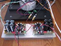
My board includes all the bells and whistles like the the cascoded VAS, and CFP drivers found on Roender's schematic (post #33 of this thread), but I keep the Vbe multiplier like MikeB's original design and use standard type of audio output transistors like the MJL3281/1302, MJL21193/21194, etc. Additionally I've added vias to the board so that jumpers can be used to configure the output transistor connections so that either BJT's or Lateral Mosfets can be used. I love the way SymAsym sounds with Magnatec BUZ Lateral output transistors.
I have two boards built and tested. The THD measurements are quite impressive, with the sound to back it up. I'll start a new thread some time this week with THD pics and more info.
Here's a pic of the completed amps.
Regards,
Al
I'm working on it. My new board works with Jfet inputs but with a single pair of output transistors at the moment but can easily drive several more pairs. I'd just would have to add about an 1" to the length of the board for each pair added.
The board design is based on MikeB's conceptual schematic post #2 of the following link.
http://www.diyaudio.com/forums/solid-state/87609-symasym-sequel.html
Roender did wonderful job of completing the design, building and testing it before moving on to his own design the RMI-FC100 found here.
http://www.diyaudio.com/forums/soli...-power-amplifier.html?perpage=25&pagenumber=1
My board includes all the bells and whistles like the the cascoded VAS, and CFP drivers found on Roender's schematic (post #33 of this thread), but I keep the Vbe multiplier like MikeB's original design and use standard type of audio output transistors like the MJL3281/1302, MJL21193/21194, etc. Additionally I've added vias to the board so that jumpers can be used to configure the output transistor connections so that either BJT's or Lateral Mosfets can be used. I love the way SymAsym sounds with Magnatec BUZ Lateral output transistors.
I have two boards built and tested. The THD measurements are quite impressive, with the sound to back it up. I'll start a new thread some time this week with THD pics and more info.
Here's a pic of the completed amps.
Regards,
Al
Attachments
I have two boards built and tested. The THD measurements are quite impressive, with the sound to back it up. I'll start a new thread some time this week with THD pics and more info.
Here's a pic of the completed amps.
Just sent you an e-mail.
Hi Andrew,
My latest board that you see in post #74 is currently using Bjts. Have not yet tested the Laterals on the new board.
Regards,
Al
My latest board that you see in post #74 is currently using Bjts. Have not yet tested the Laterals on the new board.
Regards,
Al
Hi AAK,
where did this happen?
where did this happen?
I love the way SymAsym sounds with Magnatec BUZ Lateral output transistors.
Andrew, here's the schematic implemented on my board.
Everything looks great except I get slight thump when powered on. I'm thinking it may having something to do with C20 and C21 having different time constants. If I look at the leds L5 turns on a slight bit before L4 which may explain why the output goes negative about a couple volts when turned on. The opposite happens when turned off, L4 turns off before L5 but no audible thump or movement on the woofer. I'll try different caps, 100uf may be to much, I'll try 47uF or a 22uF to see what happens.
Here's a couple THD plots from the amp at 1Khz into 8 ohms at 40 watts. My soundcard doesn't have the cleanest response so I'll post the inputs THD as a reference. What's impressive is that the amps output is just like the input at any frequency up tp 20Khz and power up to 100 watts into 8 ohms, or 140 watts into 4ohms. The cascoded VAS gets rid of all the even harmonics, and driver CFP appears to get rid of the odd harmonics.
Al
Attachments
- Status
- Not open for further replies.
- Home
- Amplifiers
- Solid State
- Symasym - Roender Style