Khron said:
That's the 10 ohm // output inductor.
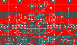
Ah, I didn't see a Zobel so I didn't consider the output inductor. Will there be a Zobel? As I recall there has been some discussion in a thread or two about locating the Zobel as close to the outputs as possible. The output inductor//resistor could be located off the main board to save space (bigger coil).
Also, many of the amps you see can be built with different devices. I remember you asked me before on my patchwork thread if it could be built with more common transistors. It's nice to have the best choice for every part but it's not critical. I'm sure the symasym wouldn't suffer a performance hit if you changed the outputs or used a different differential pair. Don't be afraid to experiment.
The Zobel is on the right side of the "bias generator" group, in the middle of the board.
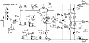
Mike Bittner mentions on the Symasym page some of the modifications possible and/or necessary (2sa/2sc devices, and different diff pair etc).
I'd rather do one thing right (or at least "right") from the first try, than fiddle around endlessly with possibilities 🙂 That's how my whole audio project got dragged through time, now reaching about 3 years without having almost anything done 100%
Khron said:The Zobel is on the right side of the "bias generator" group, in the middle of the board.
What can I say - I'm blind😱
Or is it that colour scheme in Eagle...
Anyway, now that I've actually opened my eyes and looked at it, it looks good. The parts are all well organized, especially in the front end.
Well i worked my way from the outputs back to the front end, so i wouldn't cram everything on a minimum of board surface. And, by people's reactions, i seem to be getting good at PCB drawing  Well, at least at this quite minor stuff 😀
Well, at least at this quite minor stuff 😀Khron,
There is enough free space on the board. Why don't you put as close as possible the two big elcos decoupling capacitors? 😉
Cheers,
Mihai
There is enough free space on the board. Why don't you put as close as possible the two big elcos decoupling capacitors? 😉
Cheers,
Mihai
I assume you mean "bring them closer to the middle of the board". Yeah, i guess i can give it a shot. Be back in a few mins 😀

Well... Which choice has precedence? 😀 Outputs or star ground? Or shoudl i try to find some sort of "middle ground"? (No pun intended 😀 )

yes. this board looks fine, Khron
we can say this is a good final board 😉
now let some people build this with 2 output pair power transistors & post some reports
we can say this is a good final board 😉
now let some people build this with 2 output pair power transistors & post some reports
Aha, i kinda thought that's what you meant about the base resistors. But i would like to hear a few more opinions about this before i change the board again
- Status
- Not open for further replies.
- Home
- Amplifiers
- Solid State
- Symasym PCB