They don't hurt. They can increase stability and for this amp, that's a good thing🙂
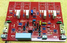
Another suggestion: There isn't a need for the ground plane you have there. You could run wide traces back to the star, especially from the 2 bigger caps on the output stage. Right now, the front end decoupling ground trace is wider than the output decoupling.
Also, look at making the output trace wider. This carried all of the current the amp provides.

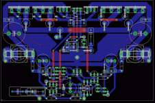
My guess is that roender thinks about keep a distance
between hot power transistors and heatsink and the electrolyt capacitors.
Higher temperatures will shorten the life of lyt-caps.
between hot power transistors and heatsink and the electrolyt capacitors.
Higher temperatures will shorten the life of lyt-caps.
I think it has more to do with the shortest path to ground form the highest source of current on the board.
lineup said:My guess is that roender thinks about keep a distance
between hot power transistors and heatsink and the electrolyt capacitors.
Higher temperatures will shorten the life of lyt-caps.
Yes and no. The main reason is to keep as small as possible the ground line between decoupling capacitors, as that line is highly polluted with half waves rectified output signal


Well done Khron.
I tried working on your .brd EAGLE file I downloaded ZIP.
But I find it difficult to change, move the wires on the PCB.
I tried working on your .brd EAGLE file I downloaded ZIP.
But I find it difficult to change, move the wires on the PCB.
I think this will be very alright.
( roender is the real perfectionist 😉 )
My opinion is we will not be able to hear difference .. not on other side of Speaker.
🙂
( roender is the real perfectionist 😉 )
My opinion is we will not be able to hear difference .. not on other side of Speaker.
🙂
Thanks, lineup 🙂
Sometimes, "perfectionism" pays off 😀
Too bad i can only get my hands on the bare boards and ferric chloride in about 2 weeks...

Sometimes, "perfectionism" pays off 😀
Too bad i can only get my hands on the bare boards and ferric chloride in about 2 weeks...
hello everyone i am new on diy and i want to built a symasym5 amplifier but i don't understand the PCB size so please help me someone and sorry for my bad english .
Take a look here: http://www.diyaudio.com/forums/swap-meet/185970-boards-sym-v2-flodins-new-symasym-5-a-3.htmlAnyone with an inside line an a set of these PCB's, i would like to get my hands on a pair...
- Status
- Not open for further replies.
- Home
- Amplifiers
- Solid State
- Symasym PCB