Colescuttle said:
I compromised with 5 pF at C14, and my amps appear to be dead stable, no matter what I throw at them.
George
Damned !
I just bought some 10 pF silver mica caps from E-Bay, I should have waited some more 😀
I plan to use it with Quad ESL's hence stability is an issue ...
Supplementary questions.hd38 said:may I connect the 2SA1943/2SD5200 power transistors about 10 cm (4 inches) apart from the PCB in order to reuse an existing amp/heatsink ?
If the output transistors are located off board on shortish wire leadouts, how should the wires be arranged?
All three twisted together, only the two high current C&E leads twisted together and the B lead separate, all three leads separate,
Should the base stopper be kept attached to the base lead like one would do with a FET, or can it be kept at the wrong end on the wire leadout, i.e. on board?
Thanks, Al.
Hi, Al:
As I have learned more and more about this amp design stuff than I had thought possible (and still can unequivocally claim the title "Dummy"), it's become clear to me that your board design was a great realization of Mike's circuit. You appear to have avoided all the bad things that a board layout can do to a circuit, even while keeping it as small as practicably possible.
When I was looking beyond chip amps I wouldn't have tried to build a pair of Sym-a-syms without your boards, so I guess again I got really lucky.
George
AAK said:Hi Colescuttle,
Congratulations on a job well done.
Al
Hi, Al:
As I have learned more and more about this amp design stuff than I had thought possible (and still can unequivocally claim the title "Dummy"), it's become clear to me that your board design was a great realization of Mike's circuit. You appear to have avoided all the bad things that a board layout can do to a circuit, even while keeping it as small as practicably possible.
When I was looking beyond chip amps I wouldn't have tried to build a pair of Sym-a-syms without your boards, so I guess again I got really lucky.
George
AAK said:Hi Sheldon,
The values for the Vbe multiplier that I selected allows for an adjustable range using R22 of between 0mv to about 50mv accross R27 and R28 with +/50V rails. That translates about 0ma to about 62.5ma across each resistor. If you use +/-36V rails you'll need drop R24 to about 240.
If you use MikeB's part values for R23,R22,R24 just make sure that R22 is set to it's lowest bias setting to prevent excessive current on the output devices when you first power up.
Al
Al aka AAK;
Thanks you . So I will be using 45 +/- 2 Volt rails and will go with the
1K, 500R and 240R combo. Though I could perhaps up the 240 to your 316.
Regards, Sheldon
I could perhaps up the 240 to your 316.
you are taking a risk that all the factors in your favour will come out right.AndrewT said:AAK's BOM calls up R23=1k0, R24=316r, VR22=100r.
if these are the Vbe multiplier resistor string, then max Vbe voltage is 1000/316+1=4.16*Vbe...................or alternatively R24 is a bit big since 4.16times is a little low for setting up the output bias if the ratio of Vbe voltages works against you.
If you adopt 1k0 & 316r it is much more likely that you will run out of adjustment before you can get sufficient bias in the output stage.
PS.
it will not do any harm to the amplifier to try 316r (or 300r or 330r). You can just swap in a new lower resistor if you find that you cannot get the bias high enough. Alternatively, you could tack a 1k0//316r on the back of the PCB.


SheldonD said:
the trimmer is only a variable resistor in this circuit not a voltage divider so it matters not. i.e. essentially there are only 2 ends in the circuit for resistor.
Thanks Sheldon, you're right of course !
I just like to secure things, usually I strive to wire the trimmer so that ClockWise increase bias and CCW decrease it.
I will check with the Symasym model I sketched for Multisim. Some forethought often prevent to blow out costly devices !
To Colescuttle :
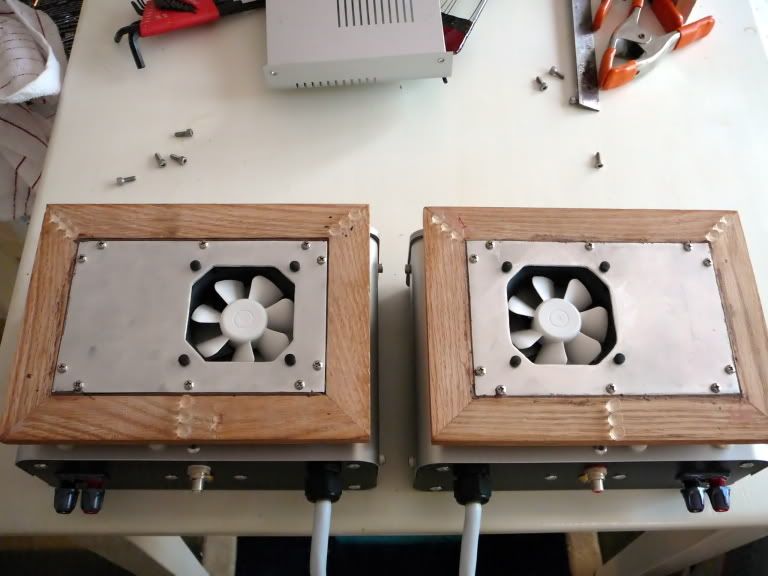
Waouh ! superb job indeed. I have somewhere in the attic a pair of FE-206 waiting in their box, looks like I have woodworking ahead ...
BTW : where did you find the V-cap (send PM, since advertising distributors is perhaps not allowed by this forum charter).
hd38 said:
To Colescuttle :
Waouh ! superb job indeed. I have somewhere in the attic a pair of FE-206 waiting in their box, looks like I have woodworking ahead ...
BTW : where did you find the V-cap (send PM, since advertising distributors is perhaps not allowed by this forum charter).
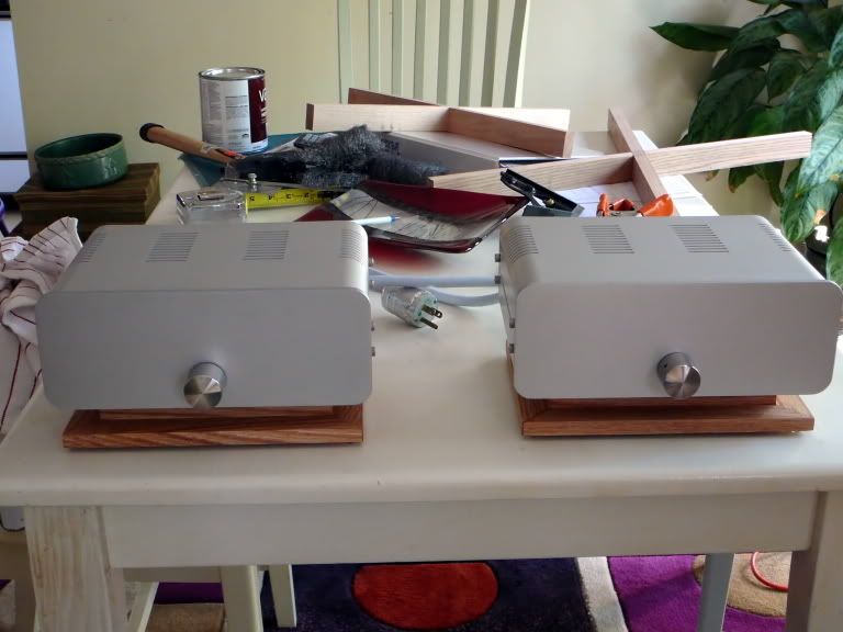
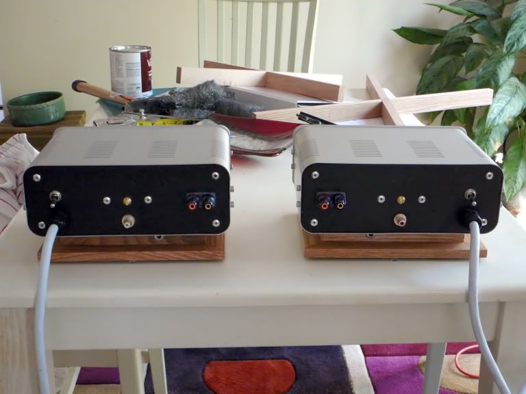
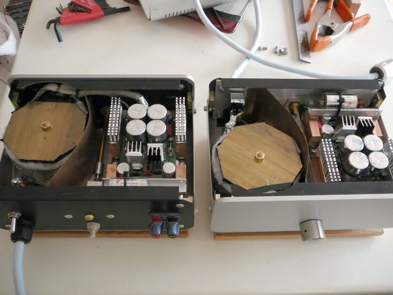
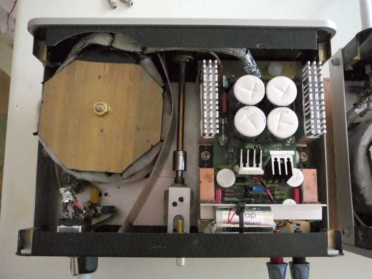
Thanks. I can't tell you how pleased and relieved I am that they're done and working. I'd been without access to my CDs (even worse, with no music but that on the car radio) for a year.
This is my fourth pair of BLHs. The first three were my own designs and were OK, although they got better as I gained experience. The problem with all of them was size - the first pair was built around an 8" driver and was huge, nearly twice the size of the PAWO. The second and third were built around 6" drivers and had more compromises in the horn section, but were still way too large for my space. I saw the PAWOs on Dave's "planet_10" website about the same time that we replaced our dog-destroyed carpets with bamboo floors. It was love at first sight. I was skeptical about its bass capabilities, but find that driven by Sym-a-syms it has too much bass unless positioned just right. Even more important, the only sound leaving the side firing mouth is true bass; there's no midrange doubling at all.
The source for the V Caps is "http://www.v-cap.com/" While not cheap, the OIMP is the most musical cap I've tried.
George
Hi,
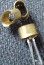
since the symasym has three matched pairs, Thought I'd put together a jig to help speed up transistor testing.
14pin dil socket (turned pin) with point to point wiring.
I set up a long tail pair with the bases connected by 10k15 (+-0.02%) resistors to a resistor ladder 20K1 to supply and 751r6 to ground.
The collectors are fed by 1k052 (+-0.01%) resistors and these are in turn fed by another 1k052 to the supply.
As I said I thought plugging the resistors into the jig would save time and just keep the lab supply to the same set supply voltage and all I had to do was read off the two collector currents until I found pairs that were close, then check the base resistors had similar Vdrop to ensure that hFE was close.
How wrong I was.
Just leaving the pair set up and leaving the room to answer the phone showed that just walking back into the room completely upset the near balanced and stabilised currents. Touching one or other To92 case upset the readings even more. My finger is heating up the case and lowering the Vbe pulling more current through the junction.
Yes, I have found 3matched pairs but I could only achieve this by leaving each test on for about 5mins to let temperatures stabilse.
Time consuming to say the least.
What other methods work? I tried fitting the To92 without handling by using long nose pliers but I found this too difficult.
I initially had matched emitter resistors fitted but they disguised differences in the matching and I decided to short them out.
When measuring transistors, i try to keep the time for measuring "constant", this gives good enough results. And i never mix measurings from previous sessions...
Mike
Mike
I also used sockets, and I tried the "as short as possible" to the "let things stabilize a few minutes" method. Both gave comparable results so I just used the short method: stick transistor in socket, take reading as soon as DMM has found its digits. After a few seconds, things indeed begin to drift.
For the small signal transistors I had no troubles finding matches to the last digit of the DMM. The output transistors were more variable, but within 5% generally.
For the small signal transistors I had no troubles finding matches to the last digit of the DMM. The output transistors were more variable, but within 5% generally.
My twopence advice (not worth more !)
1st : special thought for my Electronics teacher who will certainly spin in his grave : he told be that a good designed circuit should never be sensible to component matching !
An old Peter Walker's QUAD II will work well even with huge resistor or tube (valve for UK freaks) characteristics discrepancies ...
From the simulations I made with Multisim, I strongly believe Symasym is a far over average well designed circuit !
It worked at first run, no time step error, unbelievable for the average Multisim/Electronic Workbench user ...
So, could you explain me why this component selection process is of utmost importance ?
Hmm ... where did I put that measurement bridge 😉
Hi HD38,
Matching is very important. All differential pairs require matching as the very concept assumes matched pairs. This is your error canceling "core" if you will. The betas must be matched.
Your teacher is wrong on this one point. Output distortion is reduced when you match transistors as well. It will "work" if you don't though. So where was the cutoff for him? Things can work, but not well. Is that good enough?
Hi Andrew,
I made something similar and posted it in two different places here. The diff pair should be at the same temperature (and you just proved it! 😀 ). So couple them. Also, measure from one collector to the other and match voltage drops. Both transistors may shift in temperature, but they will drift together. My jig works great.
Hi MBK,
I found that my measured betas with a meter ike you are doing was only a pre-selection. The long tail pair jig then does a great job. Mine is selectable for tail current. You could make it continuously variable if you wanted. I may possibly make one that will sweep.
-Chris
OK anatech, but your argumentation is hence in favour of "on chip devices" compared to discrete designs since the best available matching is the one obtained with controlled diffusion within the same silicon wafer ...
Hi HD38,
Yes, matched pairs on one substrate would be the best (ie MAT series). But only the pair, no other parts allowed that may cause a temperature gradient across the chip. 😉
A diff pair on a chip or on the same substrate with a heater and regulator for the heater would be okay as long as complete isolation is achieved and no temperature gradient across the input pair. This would have the effect of keeping the transistors at a constant temperature. I just don't like really hot (= noisier).
The thing with differential pairs, or long tailed pairs, is that the primary assumption is that those transistors are matched. That is the premise of their existence. A lack of a match between them will degrade the performance.
The degree of match required between other components depends upon how much of a difference the match will make to the performance of that circuit. Sometimes it doesn't matter to the outcome of the operation (ie: cheap amp) and sometimes the match simply does not have a great effect. When they do have an effect, steps should be taken to ensure that the matching is done. If you don't, then you are accepting inferior performance. The circuit still works though. That would be a choice we are all free to make.
-Chris
No. That statement is far too wide and does not agree completely with what I said.OK anatech, but your argumentation is hence in favour of "on chip devices" compared to discrete designs since the best available matching is the one obtained with controlled diffusion within the same silicon wafer ...
Yes, matched pairs on one substrate would be the best (ie MAT series). But only the pair, no other parts allowed that may cause a temperature gradient across the chip. 😉
A diff pair on a chip or on the same substrate with a heater and regulator for the heater would be okay as long as complete isolation is achieved and no temperature gradient across the input pair. This would have the effect of keeping the transistors at a constant temperature. I just don't like really hot (= noisier).
The thing with differential pairs, or long tailed pairs, is that the primary assumption is that those transistors are matched. That is the premise of their existence. A lack of a match between them will degrade the performance.
The degree of match required between other components depends upon how much of a difference the match will make to the performance of that circuit. Sometimes it doesn't matter to the outcome of the operation (ie: cheap amp) and sometimes the match simply does not have a great effect. When they do have an effect, steps should be taken to ensure that the matching is done. If you don't, then you are accepting inferior performance. The circuit still works though. That would be a choice we are all free to make.
-Chris
MBK said:......I also used sockets, and I tried the "as short as possible" to the "let things stabilize a few minutes" method. Both gave comparable results so I just used the short method: stick transistor in socket, take reading as soon as DMM has found its digits. After a few seconds, things indeed begin to drift........Hi,anatech said:...........The diff pair should be at the same temperature (and you just proved it! 😀 ). So couple them. Also, measure from one collector to the other and match voltage drops. Both transistors may shift in temperature, but they will drift together. My jig works great.
I have previously used the quick method and took a reading at DMM settling time and again after a fixed delay of about 10seconds. Most of my "weighting" is based on the ten second reading.
When done as a single device in a socketted jig, the steepness of the slope with temp and the continuing (cooling) changes over minutes is not so obvious.
But my single device measuring method was quick and did do for initial sorting. But when closer matching was required I remeasured these "selected" devices and matched to more accuracy but using the quick method.
I wanted a bit more precision so decided to measure the LTP pair in a new jig. It is now very obvious that the temperature of my finger and how long it took to insert the device in the socket would swamp all useful data from my old method.
My new method would be great if it were not for the excessive time it takes.
I tested at 1.4mA (input pair of symasym) and Vce~15V (lab supply~22V).
Chris,
what style of jig arrangement are you using and what component values have given you success? How do you couple a pair together if one is the reference for all the other DUTs? How can you do this quickly and without handling the devices (ref nor DUT)?
anatech said:Hi HD38,
No. That statement is far too wide and does not agree completely with what I said.
Yes, matched pairs on one substrate would be the best (ie MAT series). But only the pair, no other parts allowed that may cause a temperature gradient across the chip. 😉
...
That would be a choice we are all free to make.
-Chris
Thanks Chris for this complete and meaningful answer.
Sorry if I were too general, I strove to be short at the risk of being caricatural ! From what I said, don't think I am a tenant of the "part is part" league. Just want to pinpoint where the effort are really to be made when keeping in mind that our poor ears and even poorer listening room acoustics are often much more to blame than a 5% hFE mismatch ... But like you say : we are free to choose.
You convinced me to, at least, match the LTP transistors !
I will use this device
being not familiar with your jigs concept !
I remember famous Class-A amplifiers projects from dutch magazine Elektor, LFA-50 Optim and LFA-150 Virgin using a special FET pair, 2SK146V if I remember well. One cannot find them now and a subsititution method is to use matched 2SK170.
MAT02 or 03 pairs were also used on some other projects. I don't now whether they are still available ...
The 2SK170 were thermically coupled together with a thin foil of copper wrapped around the plastic cases.
Is that the method you use to couple Q1 and Q2 BC547C (from schematics) or 2N5551 (from BOM) ?
BTW : do you use matched BC547C or 2N5551 ?
Hervé
True, LTP matching is even better than what I did (had a discussion with Chris on that before, but when I did my matching I just did Vbe, hFE and Ic matching). All I meant to say is that one can get pretty close results on this.
- Home
- Amplifiers
- Solid State
- Symasym 5.3 "AAK model" builder's thread