Invitation
*I put this post on the Full Range forum, so I guess a copy should go here, too.*
I've got to get back to my parts sale, and my mail server has been balky for the last couple of days, and I'm somewhat embarrassed by this post, so I'll try to be brief (not my forte).
For 40 of my 60 years I did semi-pro vocal work. Mainly chorus, but occasionally a lieder solo or two. As any vocalist will tell you, that means I both hear and listen pretty well. I've also found that two things put me in direct touch with God - backpacking in mountainous wilderness and music. So, for me, listening to music is an intensely important and meaningful activity, and I am very sensitive to anything in the sound that distracts me from the spiritual/emotional experience.
Most of the components of my system were still new when I finally got the Sym-a-sym monoblocs working, so one thing I can tell you is that I'm now a believer in the "breaking-in" phenomenon. (It makes sense, I guess, the flow of current slowly "repairing" the myriad metallic fractures and discontinuities that occurred during the manufacturing/construction/setting-up process.)
But I really wasn't ready for what I'm (not?) hearing now, or the fact that something is better about the sound every day that I listen. And it's not just me. Yesterday, I was sitting on the sofa, transfixed, until out of the corner of my eye I noticed that my Border Collie and Greyhound were both sitting up, necks extended, ears erect. They were listening. I know they were listening because they were turning theirs heads slightly in order to follow the creatures and machines moving between the speakers on one of the musical tracks of my old Chesky test disk.
Anyone who ventures close to Cary (Raliegh), NC, please drop me a line and I'll tell you how to get here. I need some human assurance that I'm not going crazy.
George
finger temperature monitor
Hi,
This temperature is as bad as I was beginning to believe.
I left a pair of transistors in the jig last night and powered off.
Switched on this morning and from cold Ic was 1.445mA. After 2minutes it had stabilised to 1.51mA (+4.5%) due to internal power dissipation of around 24mW per transistor.
I applied my thumb and finger around the To92 and held until the rise in Ic had almost stabilised (about 2mins again) and Ic was now 1.69mA (+11.9% on top of the 4.5% earlier). Yes, the finger induced temperature error is 2.6times worse than the internal heating effect.
It took 3minutes after letting go for Ic to fall to 1.53mA and still falling all be it, slowly.
I re-applied my finger for 5seconds and Ic went back up to 1.645mA and fell to the same 1.53mA after about 2 further minutes.
I appears that handling with warm fingers completely ruins any attempt to match/measure To92 bc550b transistors.
My old quick method is scrap.
How do we avoid handling and insert To92 into sockets to allow sensible measuring at real operating temperatures?
Re: finger temperature monitor
Tweezers? Of course I am nowhere near ready to try matching my own.
AndrewT said:...How do we avoid handling and insert To92 into sockets to allow sensible measuring at real operating temperatures?
Tweezers? Of course I am nowhere near ready to try matching my own.
Re: Re: finger temperature monitor
I have already tried long nose pliers, but I found that too difficult.
Maybe I should submit myself for re-training?
How thick would gloves need to be? thin cotton/silk may conduct too much heat, but able to "feel" what is happening during the insertion process.
Hi,BobEllis said:
Tweezers? Of course I am nowhere near ready to try matching my own.
I have already tried long nose pliers, but I found that too difficult.
Maybe I should submit myself for re-training?
How thick would gloves need to be? thin cotton/silk may conduct too much heat, but able to "feel" what is happening during the insertion process.
How about some sort of jig? I'm thinking a big SIL connector you load up with a dozen or so devices, and a three way switch to select between them. Then you can start testing the ones you loaded first whilst the others are getting back to ambient.
That is not as daft as some folk might think.pinkmouse said:How about some sort of jig? I'm thinking a big SIL connector you load up with a dozen or so devices, and a three way switch to select between them. Then you can start testing the ones you loaded first whilst the others are getting back to ambient.
A 0.1pitch SIL with twelve devices loaded. The first is REF and the other eleven are DUT. Only needs a 36way SIL and two three way sockets flex wired into the jig.
Swap the three way socket between each of the DUTs to take a reading.
For the cost of a SIL strip, one could have three or four 36way SILs loaded up and the REF on a separate three way socket.
The turned pin DIL has pins that are too small diameter for a normal 0.1pin pitch connection to lock on to.
Any ideas for a suitable SIL strip in the UK that has pins that are big enough for socket connectors?
Hi Andrew,
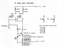
I use a pair of inexpensive four position sockets. They are mounted adjacent to each other as you would set up a diff pair (guess what I was thinking?). I use a big alligator clip to hold the transistors together for thermal coupling. I will use heat sink grease if I am being very careful. They are set up with a matched pair of resistors in each collector / drain and also in the base / gate lead. I'll include a diagram. Bear in mind that I labeled the current select positions reversed.
A CCS regulates the tail current and is settable with a dual header strip and a short (as used on computer boards). They can be added together to select current levels. The current setting has some error term at the higher levels if you want to correct the resistance used.
The trick is to measure between the drains for a null. If they are at the same temperature, this is all you need. You can also measure across the base resistors and collector resistors to figure out BJT beta at different current levels.
Keep in mind it's a simple circuit. I use an HP 6236A or 6237B to run it. I do tend to test at a D-S (C-E) voltage around 10 VDC. This is in keeping with most actual circuits. I don't care what the specs say the devices do at 5 VDC, I never run them that low.
I did match some parts quickly for EC8010, but I don't know how they worked out for him. I suspect I have to allow more time for the parts to equalize in temperature.
-Chris
Attachments
Hi Al,
The switching should be done electronically. If you could load it up and run all the parts, it would reduce the settling time. It's just that the premise I used was that the parts would actually be a differential pair.
If you look at mine, it can be improved. I designed and built in within an hour and didn't actually expect to use it. I am, so I will need to rebuild it at some point.
-Chris
That would work as long as you placed a metal bar with holes (blind) for each device and held it at some warm temperature (say, 25 °C) so that it didn't self heat. Otherwise you still need to allow time for the parts to stabilize in temperature.I'm thinking a big SIL connector you load up with a dozen or so devices
The switching should be done electronically. If you could load it up and run all the parts, it would reduce the settling time. It's just that the premise I used was that the parts would actually be a differential pair.
If you look at mine, it can be improved. I designed and built in within an hour and didn't actually expect to use it. I am, so I will need to rebuild it at some point.
-Chris
Hi,
Chris seems to get stability from his set up. I tried measuring collector to collector and the mV wanders all over the place. -20mV to -5mV in half a minute or so and back again with little ripples in the journey. (the difference tells me this is not a good match but all i need to do is find a pair that has a similar error).
I wonder if the real power amp LTP wanders like this? Most are not thermally coupled and most do not have a regulated supply.
The major difference between Chris' and mine is the CCS and thermal coupling.
The CCS is easier than building up a SIL based jig. So I'll try that first.
It is just possible that mains voltage causes tiny voltage changes in the lab supply and these impinge on the resistor ladder voltage feeding the base.
The SIL idea still works. Just unclip the bulldog, slide along to the next DUT, re-attach the 3pin plug, switch on the current & measure again.
Chris,
thanks for taking the time to provide those details.
Hi Andrew,
The CCS really helps settle things down as the pair will share a set current. This greatly reduces small shifts in your power supply.
Yes, this is how they operate in the real world too.
When I install pairs of matched parts, I use some thermal compound between them and use heat shrink tubing to keep them attached. I stick the leads in a proto-board (about all they are good for) and shrink the tubing there. Once cool they are pretty stable.
Anyway, if this quick little jig helps anyone out, then great. I find that it works for me and it's much better than trying to measure each part. I used to do that, not any more. The jig agrees with real life. The original reason I built it was that some pairs I matched did not seem to be matched in circuit. This jig conformed to what I saw in real circuits and so became a great way to confirm matches. Then I noticed it was far more sensitive, so I skipped the measure stage completely. I do measure one to get an idea what the beta is (for BJTs). You have to accept that absolute beta varies a lot. Getting a beta match that tracks the other is far more important.
-Chris
HELP! I really hate this.
Back to "Dummy Alert" posts.
I just took a lunch break, and decided to fire up my wonderful sym-a-syms and Go South.
Immediately I noticed that the channel balance was off. With the volume control set the same on both channels the left channel channel was a good bit louder. I tried a test disc with a balance track and the result was the same, with the center image floating near the left speaker, so I switched interconnects at the processor end and tried again. Same result, and it was at that point that I noticed a sharp turn-on thump, then a big DC surge on the right channel (large forward movement of the cone, then settling back slowly). It's got to be the amps, but I'm at sea here. Could anyone suggest what might be wrong with my right monobloc.
George
Hi George,
About all we can say right now is that your DC offset was corrected slowly. You could see the time constant in action.
I would check for poor solder connections. It might be worthwhile to use some PCB flux and resolder the lot. You should not need to add any solder unless the joint is "dry". After soldering, clean all flux and whatever else off with lacquer thinner and a tooth brush.
It is possible for one of your signal transistors to fail leaky or partially open. Rare.
-Chris
Thanks, Chris.
The amps have at least a hundred hours on them. When last I tested, the outputs of both amps showed 6mV DC with shorted inputs. Would a bad solder connection show up only now?
George
The amps have at least a hundred hours on them. When last I tested, the outputs of both amps showed 6mV DC with shorted inputs. Would a bad solder connection show up only now?
George
Hi,
I tried Anatech's method of CCS and bulldog clip.
Short term tability is much better. The pair also become temperature stable more quickly.
Still a bit slow needing at least 30seconds to nearly settle. But consistent.
Went back over previous nights DUTs and found most results were out by quite a margin (+-2% of Ic) but very quickly found a supermatched pair and left them running on extended test. Same result, matching Ic+-0.2% and gain +-0.5% and identified a matched pair (+-1% on both parameters).
What did come from this, is that the supermatched pair tracked each other fairly closely as test voltage was adjusted 31V down to 25V and also at three test currents.
Whereas a pair that are out by +-2% on IC do not track as CCS current is changed. I have three CCS emitter resistors giving 0.94mA, 1.33mA and 1.72mA combined they give 2.66mA or 3.05mA straddling the Symasym 2.8mA
Remember you're dealing with the forum's lowest common denominator, here.

Hi, Ryssen:
I was assuming that a bad solder connection is a bad solder connection and would show up right away.
George
Ryssen said:
Why not?🙄
Hi, Ryssen:
I was assuming that a bad solder connection is a bad solder connection and would show up right away.
George
Hi George,
No. Bad solder connections can take years to rear their ugly heads.
The first rule of troubleshooting is: Never assume anything!. I like to start fresh and write down measurements or only things I can prove are true. Saves a lot of time.
Hi Andrew,
I'm glad that worked out for you. You could make it variable too.
Anyone up for modifying that circuit to accept a sawtooth in? You could then quickly see tracking. My idea is okay for onesy - twosy stuff. You fellas should take the ball and run with it. Make it more useful.
-Chris
Hi Colescuttle,
I recently repaired a TV set that was over ten years old, and sure enough it was a bad solder joint. It can happen anytime.
It would be good idea to touch up all the solder joints. And then remove all the remaining solder paste on both sides of the board. If it turns out to be cold solder joint I would do the same to the other amp. Hope this helps.
Regards,
Al

no, I like the jumper/s selecting a combination of fixed currents.You could make it (CCS) variable too.
I made up a negative CCS first and could not understand why it didn't work (selected a 2sa instead of a 2sc - oops) but when I reversed the LED all worked properly (some BJT are surprisingly robust with reverse polarity). Then had to make a positive CCS to test the NPNs.
Now all I've got to do is find 18 matched pairs for the six PCBs.
- Home
- Amplifiers
- Solid State
- Symasym 5.3 "AAK model" builder's thread