I'm doing extensive simulations on this design and find its performance to be very good. My ultimate objective is to increase the rail voltage to 56 volts, double the output transistors (using higher power units).
In it's original state, it sims very well with low THD of 0.008% at 1000Hz at maximum output.
I'm trying to retain the good performance with the changes that I have planned. One of the things I don't like is it's low maximum input due to it's high gain.
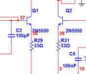
For the original design, I've changed the values of feedback resistors (as pictured) to 1.2K and 20K from 499R and 22K. This will lower gain to the point where maximum input voltage is 1.2Vrms.
With 35 volt rails, max power output would be 46 watts into 8 ohms.
For my higher power model, the new feedback resistor values are 732R and the 22k stays the same. This will give 140 watts into 8 ohms or 280 watts into 4 ohms.
In it's original state, it sims very well with low THD of 0.008% at 1000Hz at maximum output.
I'm trying to retain the good performance with the changes that I have planned. One of the things I don't like is it's low maximum input due to it's high gain.
For the original design, I've changed the values of feedback resistors (as pictured) to 1.2K and 20K from 499R and 22K. This will lower gain to the point where maximum input voltage is 1.2Vrms.
With 35 volt rails, max power output would be 46 watts into 8 ohms.
For my higher power model, the new feedback resistor values are 732R and the 22k stays the same. This will give 140 watts into 8 ohms or 280 watts into 4 ohms.
Attachments

Hi John,
Standard operating level for unbalanced RCA connectors is -10 dBm, or around 0.316 mV rms for 0 Vu. Obviously this is the "semi pro" tape machine level. I find it's close the the actual average levels. Mike originally stated that the gain was high since he used a passive volume control in his system.
It is sensitive but also has a low input impedance.
-Chris
Edit: John, you do not want to play with the feedback levels. You would have to figure out the proper compensation again on your own.
I'll re-iterate Anatech's warning.
The Symasym is set up to provide the correct feedback and compensation for that particular set of input/NFB components.
Be prepared for a few/lot of changes to component values if you change the feedback ratios.
Particularly note that reducing the gain requires more feedback.
More feedback inherently extends the closed loop frequency response.
That in turn decreases both the phase and gain margins.
All Mike's good work is then out the box.
+-56V using a 2pair output stage is stretching things. I don't believe your targets of 140/8 280/4 are achievable.
MJL21193, put a resistor divider at the input of your symasym. Do not decrease gain by change of feedback ratio.
AndrewT said:
+-56V using a 2pair output stage is stretching things. I don't believe your targets of 140/8 280/4 are achievable.
Hi Andrew,
For what it's worth, my simulation with the reduced gain and higher voltage devices throughout (2N5550 and 2N5400 replace MPSA18, BC546, 2N5551 and 2N5401. BD139 replaces BD135) runs with identical performance to the original.
Having simulated a great many circuits with it, I trust it's results enough to proceed.
The increase in rail voltage will most definitely give me 140 W @ 8ohms with no problems. 280@4 might exceed the SOA of 2 pairs of the MJL4281A and MJL4302A. This I would have to calculate. Addition of another pair of output devices is not a big problem though. A 4 ohm load for this was not my objective.
Long and the short of it is that the original circuit for this amp is unsuitable for my needs without changes. Connected to any of my equipment as is runs the very likely risk of clipping.
That's an unnecessary risk in my opinion.
Hi,
2pair will eat 8ohm loads without a sweat.
3pair gets very close to 100mS SOAR for 60degree phase angle 4ohm loads.
In a domestic situation and keeping the sink warm and never hot, 3pair should survive a severe 4ohm speaker load.
2pair will eat 8ohm loads without a sweat.
3pair gets very close to 100mS SOAR for 60degree phase angle 4ohm loads.
In a domestic situation and keeping the sink warm and never hot, 3pair should survive a severe 4ohm speaker load.
From MikeB's website:
'If the gain is too high because symasym is driven from preamp, R30 can be increased from 499ohms to 1k, but in this case R16/19 (22 or 33 ohms, not on schematic, REs to Q1/2) are required to keep feedback at same level and symasym stable.'
'If the gain is too high because symasym is driven from preamp, R30 can be increased from 499ohms to 1k, but in this case R16/19 (22 or 33 ohms, not on schematic, REs to Q1/2) are required to keep feedback at same level and symasym stable.'
Hi,
I have been comparing component values between AAK BOM and v5.3
There are some surprising differences.
I wonder if I have the correct AAKpdf?
r26=33r or 150r,
vr22=1k or 100r,
r4=4r7 or 10r,
v5.3 value first, AAK second in the preceeding list.
I have been comparing component values between AAK BOM and v5.3
There are some surprising differences.
I wonder if I have the correct AAKpdf?
r26=33r or 150r,
vr22=1k or 100r,
r4=4r7 or 10r,
v5.3 value first, AAK second in the preceeding list.
where do the extra driver REs go? between u$5 emitter and the junction of r1 & r26/c6?spind said:From MikeB's website:
'If the gain is too high because symasym is driven from preamp, R30 can be increased from 499ohms to 1k, but in this case R16/19 (22 or 33 ohms, not on schematic, REs to Q1/2) are required to keep feedback at same level and symasym stable.'
AndrewT said:
where do the extra driver REs go? between u$5 emitter and the junction of r1 & r26/c6?
Andrew, they are simple degeneration resistors to the input devices, lowering the gain of the input diff amp.
They go to the emitters of q1/q2.
Mike
spind said:REs to Q1/2) are required to keep feedback at same level and symasym stable.'
MikeB said:..simple degeneration resistors to the input devices, lowering the gain of the input diff amp.
They go to the emitters of q1/q2.
Like this?
Attachments
Hi Andrew,
With my board you need to use for R26 150 ohms to keep the drivers thermally stable since their not mounted on the main heat sink.
It also wouldn't hurt using a small heat sink for each driver especially if you use +/-50V rails. You'll find the small heat sinks listed on the BOM.
Regards,
Al
With my board you need to use for R26 150 ohms to keep the drivers thermally stable since their not mounted on the main heat sink.
It also wouldn't hurt using a small heat sink for each driver especially if you use +/-50V rails. You'll find the small heat sinks listed on the BOM.
Regards,
Al
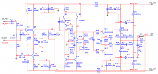
I have the schematic that I worked up to show, then I'll stop bothering you fine gentlemen.
Some specs:
Input sensitivity: 1.2 Vrms
Power: 143 Watts, 8 ohm; 285 Watts, 4 ohm.
THD: 0.023% @ max output
THD: 0.003% @ 15 watts output.
DC offset at output: < 3 mV @ full output.
Simmed with the MJL3281A and the MJL1302A. MJL4281A and MJL4302A are the planned output devices.
Have a look, make a comment (or not).
I wanted to put my ideas in front of the people that are intimately involved with this excellent design.
Thanks.
Attachments
From my experience I'd be very careful when using lower beta input differential devices. I used 2N5551 and my batch had a rather low beta, and the result was a massive turn on thump. Using Mike's original suggestions (I use BC550 now) fixed that.
If you are concerned about clipping, a move from 50 to 56V changes practically nothing; 56/50 works out to just +1 dB headroom. Even the step from Mike's original 35V to 56V only gives you +4 dB while generating all sorts of issues. Recall, 100 W is just 3 dB up from 50W.
The easiest route is probably to bridge two 35V modules (only if your speakers are strictly 8 Ohms) and use Mike's original circuit w/o changes. That gives you +6 dB headroom and will be noticeable.
MBK said:
a move from 50 to 56V changes practically nothing;
The easiest route is probably to bridge two 35V modules
Hi,
One of the reasons I want 56 volt rails is because I have a 750VA 40-0-40 transformer and nothing to do with it.
I never have been the type to take the easiest way.
Of the various amp designs that I simmed for use at this rail voltage, this one gave the best results (so far).
I have seen lots of examples of the 2N5550 being used for input. I could probably get away with leaving the BC546's in there. Pushing it though.
Any recommendations for a higher voltage, higher gain device?
Consider also that I have reduced the gain by substantial amount.
Thanks.
Hi Mjl,
R21 & R22 shared between the three outputs does not look right.
How about a separate base stopper resistor for each base pin?
There is something wrong with your simulated model. -0.015db for a load change from 8r0 to 4r0 is just not achievable.
I used a 1kVA 40-0 & 40-0 and it gave +-58.4Vdc when fed with nominal 240Vac while Ib is set to 210mA using 3pair of MJL4281/4302. The Leach 3pair delivered 311W into 4r0 (35.3Vac). You should get close to that. Q5 is going to have to work pretty hard to get sufficient current into the two stage EF output. It will also see the reactive load and the phase angles imposed by the load. A To92 device might be struggling.
R28 could probably be reduced, maybe even substantially. Try 5r6 and then 3r3.
C4 (100uF) sets the high pass filter. It should be set by the input filter. This needs altering. C4=220uF would be OK. Alternatively DC block the source with a second 4.7uF cap. That would raise the input filter to 51mS (F-3db=3Hz)
Why is R9=56r?
R15 @ 2k0 forces the current through the resistor ladder to be less than 1mA. I prefer more current if using a low gain transistor for the multiplier.
Mike,
do you have a view on this?
AndrewT said:
R21 & R22 shared between the three outputs does not look right.
How about a separate base stopper resistor for each base pin?
I can do that. Certainly won't hurt.
There is something wrong with your simulated model. -0.015db for a load change from 8r0 to 4r0 is just not achievable.
It's a purely resistive load I'm using - either 4 ohm or 8 ohm.
I used a 1kVA 40-0 & 40-0 and it gave +-58.4Vdc when fed with nominal 240Vac while Ib is set to 210mA using 3pair of MJL4281/4302. The Leach 3pair delivered 311W into 4r0 (35.3Vac). You should get close to that.
In real life, I'm only getting 56 volts from this transformer (smoothing caps in place).
As for power output, I'm seeing 33.76V at the output, that's with the 1.2Vrms input.
Q5 is going to have to work pretty hard to get sufficient current into the two stage EF output. It will also see the reactive load and the phase angles imposed by the load. A To92 device might be struggling.
I looked at that early on, and thought the change to the higher voltage, higher current device could cope with it.
Any thoughts on a suitable replacement?
R28 could probably be reduced, maybe even substantially. Try 5r6 and then 3r3.
I'll change it to 5.6 ohm. TBH, I have found this to be an area where, given the parallel coil, there's not much discernible difference.
C4 (100uF) sets the high pass filter. It should be set by the input filter. This needs altering. C4=220uF would be OK. Alternatively DC block the source with a second 4.7uF cap. That would raise the input filter to 51mS (F-3db=3Hz)
This was changed early on and was left in accidentally. I'll change it to 220uf.
Why is R9=56r?
Ground loop isolation.
- Home
- Amplifiers
- Solid State
- Symasym 5.3 "AAK model" builder's thread