Hi Ryssen,
Is that 1pair or 2pair in the output stage?
That 2ohm result is showing that does not make a good 4ohm speaker capable amplifier.
1pair output stage using 150W devices will make a good 8ohm capable amplifier. Don't even think about using severe 4ohm speakers. A moderate 4ohm speaker may be driven well but the SOA excursions will be frequent and risk failure, particularly if the devices are allowed to get hot.
Even 1pair of 200W & 230W output devices will struggle to drive 4ohm loads.
No,not 1khz for longer periods,not my kind of music..😀 😉Unless you are planning to play exactly that frequency where your speakers dip down to 2ohm for a long time, NO!
It´s one pair/channel.Is that 1pair or 2pair in the output stage?
I developed Symasym on 4ohm speakers, as long as you do not exceed the suggested 36v supply, this should not be a problem...
Mike
Mike
mike b.
How many output transistors will the current aak model of mike b's amp handle with the standard drivers. It seems another pair might not be a bad idea just to be on the safe side. thanks tad
How many output transistors will the current aak model of mike b's amp handle with the standard drivers. It seems another pair might not be a bad idea just to be on the safe side. thanks tad
Justa want to make it clear that the torture test i made in 2ohm with the working channel did NOT destroy it,it is playing like before.🙂
Hi Ryssen,
not destroyed, but current strayed beyond the DC SOA into 2r3.
Into 4r3, the 45degree reactive load strayed half way to the cold 100mS SOA. 4r3 60degree reactive and with a warm output stage goes outside the 100mS SOA.
Basically this amp runs out of SOAR and current ability into low loads and to some extent relies on sagging supply rails to reduce the SOA excursions.
I suspect you used a 30Vac transformer, with >=+-41Vdc supplies to get those power results.
Expect excellent (and reliable) current delivery into any 8ohms speaker.
I plan to try MJL4281/4302 using +-40Vdc supplies into 8ohm.
Hi Andrew,
I'm not saying this is a good design choice, but it works. 😉
-Chris
Most commercial amplifiers rely on this. I can't tell you how many designs I've looked at that should blow up, and the sagging supply is the savior. Not entirely a bad thing since the loss in power is not significant.Basically this amp runs out of SOAR and current ability into low loads and to some extent relies on sagging supply rails to reduce the SOA excursions.
I'm not saying this is a good design choice, but it works. 😉
-Chris
Yes,it is 2x30ac and at least on idle it is 44,5v dc,havent checked it at full load.I suspect you used a 30Vac transformer, with >=+-41Vdc supplies to get those power results.
When testing I used my iAudio flac player to play 1khz sinwave,it has got stepps in the volumecontrol,adjusted it to the step without clipping,so it might differ a few watts up, if I´d use a stepless volume.
So at higher voltages,more than 36vdc it might be a good idea to use double output transistors,like tryonziess says.At lower loads 4 ohms and down...

If it´s "plug and play" sommeone with more knowledge that me might know..🙂
BOM for this amp?
Hello all,
While I am waiting for PCBs from Ryssen, I would like to collect the rest of the components. Did anyone has the latest BOM for this amp? Also I am going to get some components from mouser for my Kumisa III plus headphone amp, and I want to combine the components to save little bit on shipping.
Did any one has mouser part numbers for this amp. The cool thing about mouser ordering is they have no minimum order, reasonable shipping charges and you can save your BOM in a project. You can build the BOM and order at your convenient time. Another cool thing is that they have BOM exporter tool, which converts part# <space> part qty into the order. Hope this info helps others.
Thanks,
Routhun
Many AAK BOM parts available.
I've finished my sym-a-syms, and have a slew of passive and active devices left over, including Toshiba drivers and output devices. I've also got some excellent meters, includng two transistor matching meters. I also have some hard-to-get tools useful in fabricating chassis. If anyone is interested let me know, and I will post a detailed description in the Market Place forum.
George
Hi George,
Two questions come to mind then.
1. Do you plan on making any more electronics things (are you keeping a matching meter for yourself)?
2. What do you have? We should figure out what you ought to keep.
-Chris
Two questions come to mind then.
1. Do you plan on making any more electronics things (are you keeping a matching meter for yourself)?
2. What do you have? We should figure out what you ought to keep.
-Chris
Hi,
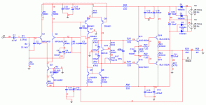
In preparation for building this amp with different components, I simulated a model of it based on the schematic in post #1. The simulation demonstrated clipping, starting at an input level of just 1.6 volts amplitude sine wave.
I post the simulation schematic for inspection. I have compared it to the original and can find no difference. Have the component values been changed during the course of this thread?
My simulation program is very accurate usually. I trust it's results, based on several different simulated designs.
Did I do something wrong?
Attachments
It should clip at much lower input voltages than 1.6V, unless you mean peak-to-peak voltage. Mike's original is designed to reach full output at 0.5 Vrms / 0.7 Vpeak, with 35 V rails.
It's easy to eyeball even w/o simulation: 32 dB or 40x amplification means, w/o considering sagging rails and voltage drops in the circuit:
50 V rails - clips at <1.25 Vpeak, <0.88 Vrms
35 V rails - clips at <0.88 Vpeak, <0.6 Vrms
Actual clipping sets on earlier.
It's easy to eyeball even w/o simulation: 32 dB or 40x amplification means, w/o considering sagging rails and voltage drops in the circuit:
50 V rails - clips at <1.25 Vpeak, <0.88 Vrms
35 V rails - clips at <0.88 Vpeak, <0.6 Vrms
Actual clipping sets on earlier.
Hi,
Yes, peak to peak. A closer look shows clipping starts at 1.5 volts, with none at 1.4V.
Just have to be careful with the preamp.
Thanks.
Yes, peak to peak. A closer look shows clipping starts at 1.5 volts, with none at 1.4V.
Just have to be careful with the preamp.
Thanks.
DONE with projects sale.
I'll prepare an itemized list of the parts and tools I have available, and post it on Market Place, although I'm very busy at work right now and it will take a few days. I'll post a notice on this forum first.
I'm pretty much done, Chris. I just needed some monoblocs for my system, and it turned out to be much more complicated and labor intensive and expensive to make a pair than I had thought. Further, although I'm waiting for the whole system to settle in before I write a final report, I don't think I could ask for better sound. So I'm done.
George
Well, fair enough George.
Watch this. Now that you know where things go wrong (so you've gained far more knowledge than you know), you will run across another project as soon as you do sell your stuff off. This is always the way.
We will be looking forward to your report, it's great when you can do something with your own two hands.
-Chris
MBK said:It should clip at much lower input voltages than 1.6V, unless you mean peak-to-peak voltage. Mike's original is designed to reach full output at 0.5 Vrms / 0.7 Vpeak, with 35 V rails.
It's easy to eyeball even w/o simulation: 32 dB or 40x amplification means, w/o considering sagging rails and voltage drops in the circuit:
50 V rails - clips at <1.25 Vpeak, <0.88 Vrms
35 V rails - clips at <0.88 Vpeak, <0.6 Vrms
Actual clipping sets on earlier.
Hi again,
I'm trying to get my head around the concept that an amplifier would be designed with such a low maximum input.
Most line output devices are in the 1.2Vrms range with some as high as 1.6Vrms. How to connect such a device, when it will constantly drive the amp to clipping?
Someone can shed some light on this?
- Home
- Amplifiers
- Solid State
- Symasym 5.3 "AAK model" builder's thread