"Glad" to hear it's not just me. I've tried braids of various brands, and suckers, and none of these really work. Every now and then I manage to really suck everything out with a braid in a neat way, the hole looking like new, and that encourages me that maybe it's just technique.
But far too often I only manage to melt the original solder, brutally pull out the old lead, and brutally push through the new one. But that's a) prone to produce burns on fingers and b) a recipe for an unreliable new solder junction. Sigh.
But far too often I only manage to melt the original solder, brutally pull out the old lead, and brutally push through the new one. But that's a) prone to produce burns on fingers and b) a recipe for an unreliable new solder junction. Sigh.
Hi MBK,
I do a lot of soldering / desoldering. What works the best for me is a soldering station set for around 300°C capable of delivering 50 ~ 60 watts of heat. Thick tip, even for sm stuff.
Add a little new solder if you need to and suck it out with a large solder sucker. Clean up with liquid solder flux (for electronics). Avoid putting pressure on the pads. The odd lead you may need to touch again with the iron and use a sharp blade to slide underneath, this separates the connection. Use pliers to straighten leads and crack any small joints (hair of solder). Your parts will come out easily without damage to the board. Clean up with wick (braid) and flux, then clean with solvent. Your pad should look new and tinned.
Always clean component leads before soldering. A little flux helps. Use only a little solder, enough to wet the joint with a small cone. Clean the board when you are done so you can inspect your work.
I have repaired many boards and poor solder joints in my years.
-Chris
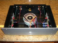
I finally have my prototype Symasym (the new mosfet version) in an enclosure. I put them in an ATI enclosure that I recently purchased from the trading post forum. I did have to modify the enclosure a bit in order to mount the boards, but it came out really nice. Now I just need to build two more Symasym modules to complete a four channel amp. Here's a pic.
Al
Al
Hi Al,
That has a chance of sounding good too.
Changes I might suggest would be to increase driver current some and eliminate those source resistors. You may need to install a resistor in the bias transistor's emitter to more closely track the FET tempco.
You should use source resistors if you need more than one pair of outputs.
-Chris
Hi Chris,
thanks for the tips. Maybe my irons weren't hot enough for desoldering, I used the 30W kind . Also, I used the thicker flux paste. Will try again until I get it right.
My soldering OTOH seems to be ok, must have done thousands of parts over the years, and only maybe half a dozen joints were unreliable. It's just the desoldering that gave me gray hair
BTW I bought your M3 tapping screws already, will wait with shipment until we see what to do with the transistors. For myself will probably use the BC550 I have in my shelf anyway.
Next week I'm away so no rush 😀
Hi MBK,
I was thinking of buying a hundred of almost every one. Let me get some money into my account. I also would like you to look for some other parts if that is no problem for you.
2SK170, 2SJ74 (BL preferred or V) and 2SC1815L, 2SA1015L (GR preferred or Y)also. I need to give you my preferred ranks as well. I can see where I'll be sending you around $100 possibly and maybe more. I am hoping you can find a good vendor for those 2SC2240 and 2SA970 (both BL, GR if I have to). I'll look up the data sheets for the rest of them. Can you check for 2SC5171 and 2SA1930 also?
Thanks again! Make sure you buy yourself something at the same time to get a discount.
-Chris
Hi Aak,AAK said:Hi anatech,
Here's rough and dirty schematic that I quickly put together. The part numbers don't match MikeB's schematic.
Al
is it intended that Q10 floats with the output voltage?
Why have you chosen a medium power type for Q5?
It's Alive!
Installed the new BD139s but I gave up on trying to set bias or even get a reading (the dmm display kept running down to zero mV regardless of whatever I do to the multiturn.)
I hooked up the pair of sacrificial rear channel speakers (them's whole purpose before were gathering dust bunnies on the bookshelf).
No pot yet so just used the slider on Foobar and hit 'PLAY".
IT WORKS! No hums or buzzes.
Initial impressions..
Left and right about the same level as far as I can tell. The speakers were crap and nasal sounding but the particular trait that I value highly in amps shone through.
The Symasym amp has got WELLY. You know, like the punch of a live kickdrum. Its more felt in the chest than heard like a Musicman bass.
Well I've never heard that before from this 70's recording of lite jazz and this time my ears perked up.
Wait till it is properly hooked sans the crocodile clips and tangled wires...
One thing though, heatsink of one channel seems to be warmer than the other...
MBK,
FYI, Koba has got a Kenwood 20MHz scope at the entrance. They want 180 singbucks for it.
Chris,
ok, will inquire more in a week's time. Off to Phuket w/the family & friends...
Cromodora,
thanks, will check it out, 180 is cheap, Kaichin sells the 20 MHz models around 350 IIRC. And congrats to your amps working! Seems your DMM is the one having troubles.
ok, will inquire more in a week's time. Off to Phuket w/the family & friends...
Cromodora,
thanks, will check it out, 180 is cheap, Kaichin sells the 20 MHz models around 350 IIRC. And congrats to your amps working! Seems your DMM is the one having troubles.
Hi Andrew,
Q10's base should be connected to ground. For the BD139, I selected primarily because it's in MikeB's original Symasym schematic. But it's also worked well with other amplifiers I've built with rails up to +/-50V. I think power wise with a Vce,Vcb of 80v, Ic of 1.5A it should be Ok.
Al
Q10's base should be connected to ground. For the BD139, I selected primarily because it's in MikeB's original Symasym schematic. But it's also worked well with other amplifiers I've built with rails up to +/-50V. I think power wise with a Vce,Vcb of 80v, Ic of 1.5A it should be Ok.
Al
Hi Al,
Have a great time off. We had an acquaintence that goes to Phuket island for vacation. He brought us back a Starbucks mug from there. Sounds like a very relaxing place.
Are you going to rent a hut on the beach?
I missed that connection, I normally connect it to ground as well. Good eye Andrew! I was more concerned with your gate drivers.
Talk to you when you are back!
-Chris
Yes,I used to have a 30w before,but I had to wait between the soldering points for it to get warm again..I used the 30W kind .
so I bougt a 48w one now its working better.Hi Ryssen,
We can get temperature controlled soldering stations made in Asia that perform really well. They cost around $100 CDN, give or take. I modify the tip grounding with a 1 Meg resistor to mains ground.
So far this station (the first one I bought) has lasted longer than any Weller Station with far less trouble and longer tip life.
-Chris
Symasymulation
While some of us are waiting for 2nd group buy conclusion
(thanks again for your efforts Ryssen)
I thought it might me interesting to play with a "virtual" Symasym : no heat, no metalwork ...
but no music
You will find the fruit of my experimentations here :
Symasymulation/
I used both of these SPICE based simulators :
National Instrument Multisim (formerly Electronics Workbench) V9
ORCAD/Capture (formerly PSpice) V10
Some disclaimer stuff (in bulk) :
Based on Mike and AAK excellent work of course !
If I unwillingly unfringed any rule/coypright etc ... I will remove all that at once (send PM)
Many evaluation versions of the above tools are available on the web, if you like these tools, buy them !
Sorry if already posted (I googled a lot to insure that w/o success)
I'm not a Spice expert at all but I will strive to answer questions ... until I receive the boards : no more spare time then 😀
Any comments / experience sharing / error reports are welcomed !
(through PM)
I plan to edit a AAK version but I have still to get / program the models for Toshiba 2SC5200/2SA1943 ... if s/o knows of ?
I'm just double checking:
I have 4 Ryssen/AAK boards
Iwould like to populate 2 of these boards with MikeB's bom.
Can I do this ?
Thanks
I have 4 Ryssen/AAK boards
Iwould like to populate 2 of these boards with MikeB's bom.
Can I do this ?
Thanks
Some pix when testing the amp in the chassie:
As you se I had to stack the trafos,as this chassie was first intended for the original Symasym pcb with one trafo.I am going to do some woodwork to cover the trafo on the underside..anyway I got a pretty good airintake now..
Testing the top,but the pcb´s are about 0,5mm to high.. will fix that,infact I had to use my dremmel to take 1mm of each output transitor to...tight..😎
The trafos are now connected in phase (minimum noisefield)
Will fix all these small details before testing the amp on some more decent speakers,at least its working now..🙂
An externally hosted image should be here but it was not working when we last tested it.
An externally hosted image should be here but it was not working when we last tested it.
An externally hosted image should be here but it was not working when we last tested it.
As you se I had to stack the trafos,as this chassie was first intended for the original Symasym pcb with one trafo.I am going to do some woodwork to cover the trafo on the underside..anyway I got a pretty good airintake now..
An externally hosted image should be here but it was not working when we last tested it.
Testing the top,but the pcb´s are about 0,5mm to high.. will fix that,infact I had to use my dremmel to take 1mm of each output transitor to...tight..😎
An externally hosted image should be here but it was not working when we last tested it.
The trafos are now connected in phase (minimum noisefield)
An externally hosted image should be here but it was not working when we last tested it.
Will fix all these small details before testing the amp on some more decent speakers,at least its working now..🙂
- Home
- Amplifiers
- Solid State
- Symasym 5.3 "AAK model" builder's thread