anatech said:What you should have done was to build this amp and simulate it. You would then see correlation between life and sim. Also keep in mind that PCB layout can make a large difference. Mike's original thread bears witness to this.
Hi Chris,
For the moment, I live in the fantasy world of simulation. Board layout can make a big difference I know, the simulator doesn't hold that against the circuit though.
I modelled the amp exactly according to Mike's schematic (pic below) and found the square wave broke down below ~4K.
Has there been component changes from the schematic I followed?
Thanks.
Attachments
Hi,
the 22pF on the NFB line has been reduced to <=10pF. The value seems to be critical to stabilising different output devices. Be prepared to use values as low as 2.2pF.
The 330pF loads to ground for the VAS have different values in some schematics, (or 220pF). These may need a bit of trimming.
the 22pF on the NFB line has been reduced to <=10pF. The value seems to be critical to stabilising different output devices. Be prepared to use values as low as 2.2pF.
The 330pF loads to ground for the VAS have different values in some schematics, (or 220pF). These may need a bit of trimming.
MJL21193 said:
Hi,
This amp will not work properly at that rail voltage. Too low.
MJL, +/-16v is no problem, symasym operates down to ~6v.
Mike
Guys,
May I know how to determine optimum value for C2?
C2=100pF, -3dB=796kHz
C2=33pF, -3dB=2.4MHz
Both have cut-off freq way beyond 22kHz. Pls advice.
Off topic question : (see attachement)
Why in audio, only a single miller capacitor is use for compensation, while in IC design RC is use most of the time?
Thanks.
Attachments

MJL21193 said:I'm too lazy (or busy) to search for this but has anyone done any real world testing on this amp? If you fine gentlemen can point the way to the results, I'd be much obliged🙂
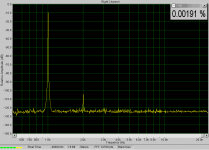
Here is one measurement, but only 1w into 8ohm, 1khz. This version used jfets as inputs, bjt version is ~6db lower in distortions.
Mike
Attachments
Ipanema said:Guys,
May I know how to determine optimum value for C2?
C2=100pF, -3dB=796kHz
C2=33pF, -3dB=2.4MHz
Both have cut-off freq way beyond 22kHz. Pls advice.
Please keep it 100pf, as input filter it serves to keep hf out, additionally it helps stabilizing, reducing impedance to q1 at high frequencies.
Mike
Hi,Ipanema said:May I know how to determine optimum value for C2?
C2=100pF, -3dB=796kHz
C2=33pF, -3dB=2.4MHz
Both have cut-off freq way beyond 22kHz.
2k0 and 100pF have an RC time constant of 0.2uS. This is below the normally recommended range of 0.5uS to 1.5uS. Some designers/builders do go as low as 0.3uS and Mike has gone lower still.
Most listeners will hear the effect of 1.5uS cutting off some of the treble. Some will prefer it this way.
Some will hear 1uS removing a little of the sparkle.
Most will not hear the effect of 0.5uS low pass filter on the input.
The other consideration is how effective the RF attenuation is.
As the low pass filter goes up in frequency so the attenuation drops, low uS time constant=low attenuation of RF.
It is a compromise between RF attenuation and passing all/most of the audio signal.
BTW,
33pF gives 0.07uS with a 2k0 series resistor. In my opinion this is too low.
Hi MikeB and AndrewT,
If I use R13=6K, then I would be able to maintain 0.2uS. Will there be any problem? I just want to save some $ as I have quite a lot of 33pF silvered mica.
As for C7, I will use 3 X 33pF in parallel. Is that OK?
Thanks.
If I use R13=6K, then I would be able to maintain 0.2uS. Will there be any problem? I just want to save some $ as I have quite a lot of 33pF silvered mica.
As for C7, I will use 3 X 33pF in parallel. Is that OK?
Thanks.
MikeB said:
MJL, +/-16v is no problem, symasym operates down to ~6v.
Mike
Maybe I should have elaborated:
My simulation shows clipping starts at 240mVrms input at =/-16 rail voltage. At +/-6V clipping starts at 59mVrms.
This clipping at normal input level could be mistaken for another problem.
Ipanema said:Hi MikeB and AndrewT,
If I use R13=6K, then I would be able to maintain 0.2uS. Will there be any problem? I just want to save some $ as I have quite a lot of 33pF silvered mica.
As for C7, I will use 3 X 33pF in parallel. Is that OK?
Thanks.
Please, don't change ANY of these caps... If you have so many, also use 3 parallel for c2.
Mike
MJL21193 said:
and found the square wave broke down below ~4K.
Sorry, this is not the case. Ignore my stupidity.😱
MBK said:I agree with Chris. The bass perception issue is quite complex. The Q of the roll off for instance does change bass perception, and here either a smaller OR a larger input cap may give you a stronger bass impression... (because it will mess with the speaker's Q). But at the discussed cutoffs, all well below 10 Hz, I don't see the coupling cap as a major factor in bass magnitude.
Other factors that are much more important include the room. Example: I used to run my speakers down to 20 Hz (EQ'd dipoles, so the cutoff and Q is at my will depending on EQ). Then I noticed that my room has a strong resonance at 50 Hz, and others at multiples: 25, 75 and 100 Hz. At 40 Hz there is a bottomless dip. Then I EQ'd the 50 Hz peak out. But after experimentation in the end I realized that I could run the system at its natural 69 Hz roll off, the 50 Hz resonance would then "EQ" and lift up the response somewhat below, and below 40 Hz my room is hopeless (the 25 Hz peak won't change your music impressions much). So, I realized things often work out in a different way, and the input coupling cap in all likelihood has nothing to do with it.
I am using 2.2 uF input caps on my Symasyms now with no discernible ill effects.
The bass perception issue is indeed complex and involves e.g. phase shifts, masking and room acoustics in general . But you may draw the wrong conclusions going from your specific room to general statements about matters?
In order to avoid too much influence from room modes which are
more "solitary" in the lowest frequency domain (and in addition could be lower than some think of because the could appear in a transverse manner e.g. from the rear left and lower corner seen from your listening position to the room´s front right upper corner) some measures are needed.
Even if effects of room moods could be diminished by equalising the signal going to the amps this measure doesn´t cure the root of the problem namely that certain frequencies (differences in air pressure) live too long if they are not killed by forcing them to pass through another media than air. Absorbers that work at lower frequencies are needed in order to tame room moods. Even tuned devices like Helmholtz resonators can be used. In the case of absorbers waves will change there speed under isotropic conditions i.e the wasted heat can´t be easily transported away.
In a room that is treated to have a fast decay of low frequencies perception of bass notes are greatly enhanced because room moods doesn´t mask or blur the following notes like in an untreated room.
If certain conditions like a large enough listening room with adequate dampening is used in conjunction with apt loudspeakers going deep and positioned in a clever way , a well chosen listening position as well as good source materials (recordings) with low frequency information, I think many people will hear a difference if a DC-coupled amp is supplemented by a high pass filter with a corner frequency of say 10 Hz and a steep cut off. My own, -as well as some other peoples experiences point in this direction. But please remember that there are some premises that have to be met in order to really hear a difference at all. It is probably not so much about instruments going low as information about the acoustics of the room where the event has taken place so it may differ with type of music.
Many listening rooms have to little damping in the low end department, thus for reasons of psychoacoustics many will not experience a difference introduced by filtering the signal. But to me even the perceived pace of the music may be affected by room tuning.
For the last seven years I have done a lot of tuning of my subs and treated the listening room in different ways. I have learned a lot and have been forced to reconsider many things.
I now even have a hypothesis that acoustic treatment to the listening rooms may influence the amps at least if they have NFB. Maybe the speakers may act as microphones as well?
Symm is working
Guys,
Found the problem yesterday. I got a reverse collector and emitter because I swap BC546 with MPSA42. 😀
With 33pF at C2 and C7, it shows a very small amplitude ~MHz region ripple at my scope when I tested it with 70kHz square wave. Increasing C7 to 66pF completely remove those ripple. The output is not connected to any load, except the scope. I'll have a listening test tonight with 33pF, 66pF, 99pF and 132pF.
Can you show me how can I test the stability of an amp? Do I need to connect to an actual load to test for amp stability?
What should the correct out biasing for this amp? I saw somewhere that it is 57mA. I don't have a distortion analyser to do the test. I'm using MJE1534/5 driver and MJL1302/3281 output.
MikeB,
Can you help to explain why 2K*100pF cannot be substituted with 6K*33pF for the RF LP filter?
Thannk you so much for help. 🙂
Hi The golden mean,
The volume of the room will partially determine the lowest supported frequency. We normally measure the diagonal in three dimensions. When doubled, this represents the wavelength of the lowest frequency supported. It has nothing to do with room modes at all. This often will couple to other volumes in a structure. This explains why you can get wonderful bass in areas outside the listening room and the bass may be greatly reduced.
Another point to consider is the fact that a transducer will decouple from the air at some frequency. It also matters how much volume of air a "piston" displaces.
What this means is that there are limits to how low you can go. Simple and that is that. You can product concussive pressures, nut this isn't the same thing as supporting a continuous tone.
Another truth is that your low frequency driver will heat more and distort as it attempts to reproduce frequencies below it's designed cutoff. This means that when you attempt to over extend your frequency range downward, you seriously diminish the transducer's efficiency (by as much as 2 dB!) and add greatly to distortion. This distortion normally takes the form of overtones and what is sometimes called frequency doubling (2nd harmonic THD). Is anyone surprised at all?
-Chris
Hi Ipanema,
If you plan on building more amps, an HP 331A/332A/333A or 334A can be had on Ebay. An HP 8903 or 339A are wonderful if you can snag one at a good price. Lovely equipment. Keep in mind that an HP has much higher frequency response than things like a Leader or Kenwood type. The HP will read higher (the truth) because it registers all the harmonics - well okay, more of them.
-Chris
That's great! Congrats.Found the problem yesterday.
A hard fault to find when you are troubleshooting your own work. I'll bet you said something that you won't repeat. 😀 I've done this also, so don't feel bad.I got a reverse collector and emitter because I swap BC546 with MPSA42.
Yes. You need a variety of inductances and capacitances after you clear the simple resistive tests. You can use a sine wave and look for bursts at zero crossings or near one or the other peak. 1 KHz will be fine for this test.Can you show me how can I test the stability of an amp? Do I need to connect to an actual load to test for amp stability?
That's unfortunate. It's the best way. 57 mA may be a little high, but this is only my opinion. I'm running around 23 mA with MJW0302A/0281A. It will depend on how close the betas are from the NPN to the PNP also. Keep in mind that I matched everything, so if you didn't you may very well need a higher bias level.I don't have a distortion analyser to do the test.
If you plan on building more amps, an HP 331A/332A/333A or 334A can be had on Ebay. An HP 8903 or 339A are wonderful if you can snag one at a good price. Lovely equipment. Keep in mind that an HP has much higher frequency response than things like a Leader or Kenwood type. The HP will read higher (the truth) because it registers all the harmonics - well okay, more of them.
-Chris
ANATECH
Are you referring to a specific device for measuring distortion or will a good o scope work just as well. I have been looking into buying a scope if it will help when building my amps. Then I will have to learn how to use it. Thanks Tad
Are you referring to a specific device for measuring distortion or will a good o scope work just as well. I have been looking into buying a scope if it will help when building my amps. Then I will have to learn how to use it. Thanks Tad
Hi Tad,
Sorry for the bad news.
-Chris
No, a distortion meter is another piece of stuff on your bench. For audio work it is really needed. The 'scope is great at looking at the residuals from the THD meter (what's left after you remove the fundamental signal). Your meter and 'scope are the most important. A THD meter and low THD oscillator will tell you things in much more detail. Most THD meters have an output so you can send that signal to a 'scope or FFT analyzer.Are you referring to a specific device for measuring distortion or will a good o scope work just as well.
Sorry for the bad news.
-Chris
Hi Anatech,
Thanks for the info on distortion analyzer. Its cheap enough to get hold of one but my working space is limited. BTW, is the PC based analyzer good enough for the job? Do you have any recommendation?
Can you point me to a good link that explain on amplifier measurement?
Is there any way to measure the phase margin of amplifier using scope?
From datasheet MJW0281/0302 looks almost the same as MJL1302/3281 albeit with slightly higher FT of the former. I shall turn down the bias a little according to your setting. At 50mA, the driver is a bit hot without heatsink.
Thanks and cheerz!
Re: Symm is working
They are not equivalent and will affect the performance of the amplifier.
It is generally safe to lower the source impedance seen by the input, but raising that source impedance may not be safe. But, I did say generally, so don't take it as an absolute rule.
If you were to propose reducing the series R and making the C larger (1k0 & 220pF) to bring back the RC time constant, then you may be OK.
Mike,
can you confirm exactly what your amp is happy with at the input and what is "best"?
these two alternatives present completely different source impedances to the non-inverting input.Ipanema said:Can you help to explain why 2K*100pF cannot be substituted with 6K*33pF for the RF LP filter?
They are not equivalent and will affect the performance of the amplifier.
It is generally safe to lower the source impedance seen by the input, but raising that source impedance may not be safe. But, I did say generally, so don't take it as an absolute rule.
If you were to propose reducing the series R and making the C larger (1k0 & 220pF) to bring back the RC time constant, then you may be OK.
Mike,
can you confirm exactly what your amp is happy with at the input and what is "best"?
Without wanting to preclude Mike's take on this, I recall on his website his explicit "OK" to run Symasym with a 22k log pot wired as voltage divider to the input. That would represent a 11k//11k = 5.5k worst case source impedance, so 6 k series should be ok (but then the source definitely has to be low impedance - no additional series R).
- Home
- Amplifiers
- Solid State
- Symasym 5.3 "AAK model" builder's thread