I must compliment "Jims Audio" 15Wx2 class A 25Wx2 class AB Ovation sx-Amplifier Current Feedback PCB set ! | eBay
I ordered the PCBs earlier this evening, and, they have already shipped 🙂
I ordered the PCBs earlier this evening, and, they have already shipped 🙂
Many thanks Bonsai 🙂
[I did check page 57... of this post... where will I find the write-up then please?]
There's a link to it in the first post - it will take you to the hifisonix website download page, else you can just follow the link at the bottom of my signature below. Read through it, especially the section on construction etc
That's a great help - many thanks Bonsai 🙂
Now to find a way to keep myself occupied whilst I await shipment of the PCBs from China....!
Now to find a way to keep myself occupied whilst I await shipment of the PCBs from China....!
I realise it is usually best to try to get everything from one supplier and I have always been delighted with Mouser's service. For those in the UK, Farnell, CPC and RS Components are also a good source of components. I got the terminals, tags and the 5A fuse holders from Farnell, as I buy from them quite often. RS has the Panasonic 220uF at £0.61 and the SMD caps which I forgot to include on my Mouser order.
Last edited:
Need help to diagnose a high current issue with one of my friend's sx-amp boards.
Prior to a mod he began, both the boards were working ok and configured for 1.4A current.
Last week I tried to fix the pcb error of Q3 base connection and applied jumper correction and was successful. Both of my boards are functioning well and all readings are much closure to the recommended values in manual.
The same was attempted by my friend and surprisingly one board he could configure and the other was started showing 5.2Amp and immediately causing fuse to blow. What do you think is the issue?
Both the boards were functioning ok prior to this and he started this jumper fix as part of a series of things he planned to do (eg., replacing matched small signal transistors, replacing 220pf cap with a quality one, 1% tolerance zener diodes etc.,) but ended up with this problem.
Where do you think he should start debug the issue? Does this reflect possibility of Q3 out of circuit due to damaged pads?
Try this:-
REMOVE R20. The standing current will then drop to between 400 and 600mA. If it does not - i.e. still much higher, then you need to check out Q3 - its probably damaged, OR you have a short between the base and emitter of Q3
AFTER you put R20 back in, measure between the resistance between the base and emitter of Q3 and adjust R6 for MAXIMUM. This will set the current to the minimum value, and you can adjust to the correct value.
Last edited:
Schematic for the power supply board?
Hi Bonsai,
The PCBs turned up today from China (Jim's Audio) and they really are of a very high quality 🙂
Do you have a schematic for the power supply PCB also please, I can only find the amp PCB schematic so far.
Thanks very much Bonsai 🙂
Hi Bonsai,
The PCBs turned up today from China (Jim's Audio) and they really are of a very high quality 🙂
Do you have a schematic for the power supply PCB also please, I can only find the amp PCB schematic so far.
Thanks very much Bonsai 🙂
Hi rbalau72
Are you referring to: The-sx-Amplifier-V2.10.pdf ?
The-sx-Amplifier-V2.10
As I can't find a schematic for the power supply PCB there...
(sincere apologies if it is staring me in the face)
Thank you 🙂
Are you referring to: The-sx-Amplifier-V2.10.pdf ?
The-sx-Amplifier-V2.10
As I can't find a schematic for the power supply PCB there...
(sincere apologies if it is staring me in the face)
Thank you 🙂
Yes, please see the one i have downloaded earlier..
https://drive.google.com/open?id=0B5rovPatezdHUVRPY2NxNXNCSTA
https://drive.google.com/open?id=0B5rovPatezdHUVRPY2NxNXNCSTA
Brilliant - thank you rbalu72
On my doc it was just appearing as a black block.
Much appreciated 🙂
On my doc it was just appearing as a black block.
Much appreciated 🙂
Matching components
Hello Forum!
With regard to matching components:
From the V2.10.pdf: The-sx-Amplifier-V2.10
as I don't have experience with this - please could someone give me a steer as to how many BC547 (BC550C) & BC557 (BC560C) transistors to buy in order to 'match'...
I guess this may sound like a daft question - but - I think I understand the idea of what to do, I have never tried this in practice however and am looking for some 'well seasoned' advice if possible!
Again - I understand the idea, and, in the case of these transistors, they certainly are less expensive per unit to buy in order to test between a number of them. How do you achieve this testing in practice please?
Many thanks for any advice Forum 🙂
Hello Forum!
With regard to matching components:
From the V2.10.pdf: The-sx-Amplifier-V2.10
For Q7 and Q8, match hFE to within 15% and Vbe to within 10 mV - if you can, tighter of course is also always better.
as I don't have experience with this - please could someone give me a steer as to how many BC547 (BC550C) & BC557 (BC560C) transistors to buy in order to 'match'...
I guess this may sound like a daft question - but - I think I understand the idea of what to do, I have never tried this in practice however and am looking for some 'well seasoned' advice if possible!
For Q8 through Q11, match hFE to within 5% or better, and Vbe to within 5 mV – in both cases, tighter is better. This is easily done if you buy a bag of these devices and then sort first for hFE, and then after that group by Vbe.
Again - I understand the idea, and, in the case of these transistors, they certainly are less expensive per unit to buy in order to test between a number of them. How do you achieve this testing in practice please?
Many thanks for any advice Forum 🙂
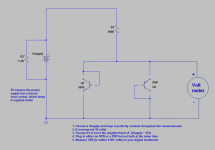
I think we (me and my friend) bought 100 each of BC550C & BC560C and their HFE is all over but could find about 15-20 pairs closely (infact identical) and selected 4 pairs for our boards from the lot. 100 pieces cost ~$6 for each type/. Used DMM to measure HFE and attached circuit to measure bve.
We bought about 20 pairs of TIS transistors (2SA1360 and 2SC3423) from Joshvi (FM on diyaudio) and could match 2pairs to about ~10-11% in hfe. This part is a bit expensive as each of this cost a $ each.. so YMMV, just an indication.
We didnt matched output transistors. Happy with the outcome which is what matters 🙂 🙂
Attachments
Hi Rbalu72
Thank you!
What a great reply - that is really appreciated 🙂
This is a great project to learn some of the 'fundamentals', as, I'm reading in focussed directions in order to understand the instructions.
Thanks also for the circuit diagram Rbalu72 - it's really helpful in understanding how and what to do 🙂
Yes rbalu72, this is what I did as reported in post 2135;
http://www.diyaudio.com/forums/solid-state/236522-sx-amp-nx-amp-214.html#post4827348
Except I used the Duoyi tester as it is very quick and easy. The SX amp works perfectly using this procedure.
http://www.diyaudio.com/forums/solid-state/236522-sx-amp-nx-amp-214.html#post4827348
Except I used the Duoyi tester as it is very quick and easy. The SX amp works perfectly using this procedure.
I realise it is usually best to try to get everything from one supplier and I have always been delighted with Mouser's service. For those in the UK, Farnell, CPC and RS Components are also a good source of components. I got the terminals, tags and the 5A fuse holders from Farnell, as I buy from them quite often. RS has the Panasonic 220uF at £0.61 and the SMD caps which I forgot to include on my Mouser order.
Thanks gcl - I'm finding that I have to use mouser / RS / Farnell so far.
Still working out how I'm going to match the transistors / how many to buy etc.......
Yes rbalu72, this is what I did as reported in post 2135;
http://www.diyaudio.com/forums/solid-state/236522-sx-amp-nx-amp-214.html#post4827348
Except I used the Duoyi tester as it is very quick and easy. The SX amp works perfectly using this procedure.
Thanks for that gcl - it seems a bit daunting spending £45 on the tester not knowing if this is the right bit of kit for me in the future (what does the future hold...?!) - it's funny now, but, I thought that I'd be able to build my first amp using a soldering iron, a multimeter and some determination 🙂
Thank you for your advice 🙂
- Home
- Amplifiers
- Solid State
- SX-Amp and NX-Amp