This thread is to document the rebuild, measurement and analysis of a SWTPC Universal
Tiger (UT) original version amplifier.
INTRODUCTION
There are many threads on here about this amplifier with many members chiming in to write
about how their amp blew up most often with lots of smoke. I built the stereo version at a
young age and blew it up a few years later while using it on the bench to measure speakers.
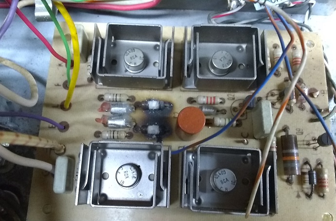
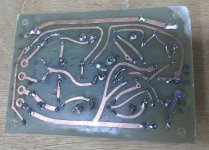
I've been fascinated all these years by how violently these amps self destruct burning the
circuit board all the way through and melting capacitors. Here's a picture of the typical damage:
Schematic: https://www.diyaudio.com/forums/att...096758143-universal-tiger-universal-tiger-gif
These are background threads about this amp, pictures:
Tiger Amp Madness!
General discussion:
Universal Tiger
Simulation:
Swtpc Universal Tiger Improved And Simulation
BEFORE PICTURES
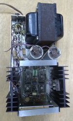
This is the before picture of the amp that I'm rebuilding:

Part way into it:
https://www.diyaudio.com/forums/att...pc-universal-tiger-rebuild-analysis-utr-2-jpg
AFTER PICTURES
This was the MKII version but I want to start with the original version since they all need
fixes to cure the oscillation problem. I'm using a home made board, by Tubelab, that has
never been powered up with all new parts. I diode tested all the semis and caps and tried
to use SWTPC parts as much as possible. This is built completely stock but R12 and R14
are upsized to 2W and the rest of the 100 ohm resistors to 1W flameproof since we don't
want the amp burning up during test. Polystyrene caps C3 and C4 are repaced with
ceramic disk so that they will not melt. The feedback cap and input filter cap are on stand
offs so that they can be easily changed for experimentation:
https://www.diyaudio.com/forums/att...pc-universal-tiger-rebuild-analysis-utr-3-jpg
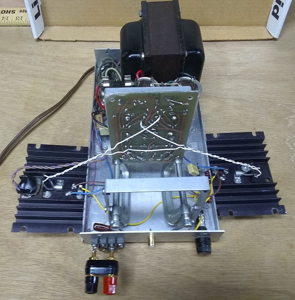
Backside:
https://www.diyaudio.com/forums/att...pc-universal-tiger-rebuild-analysis-utr-4-jpg
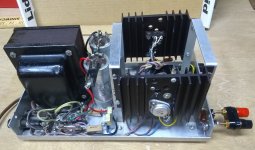
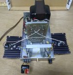
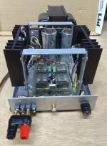
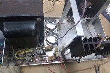
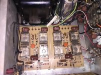
Completed amp:
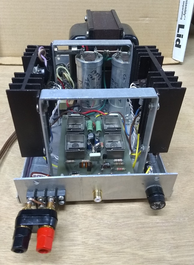
Wires are long enough to lay heatsinks flat and raise PC board up for easy access to both
sides. Small C-clamps are used to stand up the PC board:
A few more pictures:
I color coded the wiring:
red B+
black B-
green ground
white Bias
yellow input/ output
https://www.diyaudio.com/forums/att...wtpc-universal-tiger-rebuild-analysis-utr-jpg
https://www.diyaudio.com/forums/att...universal-tiger-rebuild-analysis-utr-left-jpg
INITIAL TEST
I brought the amp up on a lab power supply, initially at +/- 28V current limited to 150 mA, it worked
fine, then to the stock +/- 42V also current limited to 500 mA. There was zero bias current in the
output stage and .32V, yes that is V of output offset. I added a bias pot and it was erratic, smooth
up to about 60 mA then jumped up to 350 mA - not a good sign. Left the bias at 50 mA but it did
not help the DC offset.
There are many ways to make the amp oscillate, and turning up the bias was one, luckily having
the power supply current limited to 500mA saves the amp from self destruction and allows
observation on the bench. The 3-5 MHz oscillation is mostly filtered out by the output inductor -
circuit should be probed just before the inductor to see the oscillation.
Thought about this a bit and we might noticed that the feedback resistor is 2.2K but the main input
to ground is 20K. Grounded the input, also for 2.2K to ground and the offset fell to .008V, much
better and agrees with theory. The feedback impedance should be raised and the input AC coupled
in order to keep the output DC offset low.
A FEW NOTES:
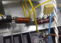
1. The output inductor measured 2.3 uH and .067 ohms DCR, it would be better to
have half or less DCR.
2. Most of the 70s UT used mica insulators that I measured as 2.5 thou thickness, there
are many comments about how 1 thou is better. I've seen a repaired UT and a Tiger
.01 with Kapton insulators that measure 2 thou thick, 1 thou is better.
Keratherm products are the modern solution but since I have 1 thou Kapton I'll probably
just use that. Link to tech info: http://www.mhw-intl.com/assets/Keratherm_Catalog.pdf
3. The MJ4502/MJ802 TO3 devices from the 70s and perhaps 80s were of all aluminum
construction. There are many reports of these TO-3 devices failing due to the aluminum's
large physical coefficient of thermal expansion/contraction with temperature. The later
TO-3s that I have from the 1990s are steel or perhaps copper base coated - I'm not sure
but they are not aluminum and should be more reliable in situations where there is a lot
of thermal cycling. The original output devices have poor safe operating area (SOA)
compared to modern devices and therefore should be replaced in any Tiger that is used
at high power or into low impedance loads.
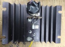
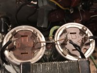
4. Simple improvement to the heat sink assembly that my brother and I noticed back in the 70s:
The stock assembly is shown here where it can be seen that the thermal sensor diode and
collector connection are made on the back side where both heat and electrical current
have to pass through the screw and nuts holding in the transistors. The screw head to
transistor, screw to nut, and nut to terminal lug are all non-gas tight connections:
https://www.diyaudio.com/forums/att...ersal-tiger-rebuild-analysis-utr-hs-stock-jpg
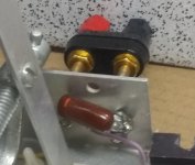
We concluded that moving the thermal sensor and collector terminal to under the screw
head was a much better way to conduct both heat and electrical current:
https://www.diyaudio.com/forums/att...iversal-tiger-rebuild-analysis-utr-hs-mod-jpg
I've not done this mod to this test amp but will do it with any other rebuilds that I do.
GROUNDING:
The grounding is somewhat convoluted in the Tiger amps and documentation
is provided below for others to follow along.
There are 5 terminal points that use chassis ground in the UT mono
block version, the stereo version is very similar:
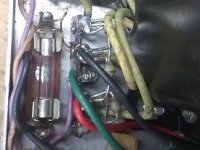
1. Diode Term Ground:
This is at the bridge diode terminal strip on the mounting terminal
that grounds the transformer center tap and the speaker terminal gnd:
https://www.diyaudio.com/forums/attachment.php?attachmentid=798553&d=1575055539
2. Emitter Term Ground:
This grounds the output transistor emitters through .1uF bypass caps:
https://www.diyaudio.com/forums/attachment.php?attachmentid=798554&d=1575055539
3. Zobel Term Ground:
This grounds the Zobel:
https://www.diyaudio.com/forums/attachment.php?attachmentid=798555&d=1575055539
4. Speaker Term Ground:
This is a chassis terminal lug at the speaker output that grounds the .1uF
across the speaker output:
https://www.diyaudio.com/forums/attachment.php?attachmentid=798556&d=1575055539
5. Input Terminal Lug:
The input RCA jack is not an insulated type and the input circuit, hole A,
is grounding to this lug.
No picture
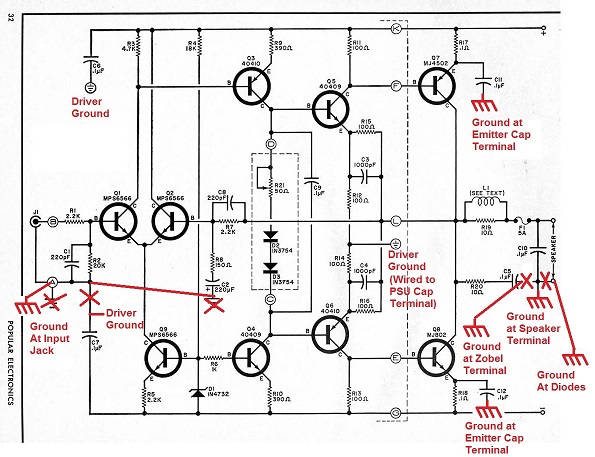
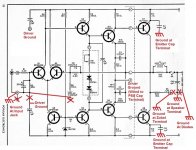
The published schematic freely uses the ground symbol without making any
distinction between chassis ground and other grounds such as the traces
on the circuit board. There are two traces on the circuit board that I'll
call input ground and driver ground. The input ground includes base bias
for the input transistor, RF filter cap (C1), and feedback network ground (C2)
and connects to hole A on the circuit board. Driver ground goes to the hole
with a ground symbol rather than a letter identifying it. There are some
errors on the schematic where, for example, one bypass cap (C7) goes to the
input ground when in reality it connects to the driver ground.
I corrected the schematic to correctly show input ground, driver ground, and
all the chassis tie points as shown below:
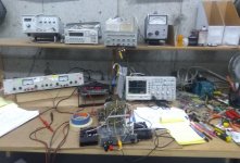
Here's the amp under test, HP lab power supply, HP function generator, Rigol Scope:
https://www.diyaudio.com/forums/att...-universal-tiger-rebuild-analysis-utm-lab-jpg
Tiger (UT) original version amplifier.
INTRODUCTION
There are many threads on here about this amplifier with many members chiming in to write
about how their amp blew up most often with lots of smoke. I built the stereo version at a
young age and blew it up a few years later while using it on the bench to measure speakers.
I've been fascinated all these years by how violently these amps self destruct burning the
circuit board all the way through and melting capacitors. Here's a picture of the typical damage:
Schematic: https://www.diyaudio.com/forums/att...096758143-universal-tiger-universal-tiger-gif
These are background threads about this amp, pictures:
Tiger Amp Madness!
General discussion:
Universal Tiger
Simulation:
Swtpc Universal Tiger Improved And Simulation
BEFORE PICTURES
This is the before picture of the amp that I'm rebuilding:
Part way into it:
https://www.diyaudio.com/forums/att...pc-universal-tiger-rebuild-analysis-utr-2-jpg
AFTER PICTURES
This was the MKII version but I want to start with the original version since they all need
fixes to cure the oscillation problem. I'm using a home made board, by Tubelab, that has
never been powered up with all new parts. I diode tested all the semis and caps and tried
to use SWTPC parts as much as possible. This is built completely stock but R12 and R14
are upsized to 2W and the rest of the 100 ohm resistors to 1W flameproof since we don't
want the amp burning up during test. Polystyrene caps C3 and C4 are repaced with
ceramic disk so that they will not melt. The feedback cap and input filter cap are on stand
offs so that they can be easily changed for experimentation:
https://www.diyaudio.com/forums/att...pc-universal-tiger-rebuild-analysis-utr-3-jpg
Backside:
https://www.diyaudio.com/forums/att...pc-universal-tiger-rebuild-analysis-utr-4-jpg
Completed amp:
Wires are long enough to lay heatsinks flat and raise PC board up for easy access to both
sides. Small C-clamps are used to stand up the PC board:
A few more pictures:
I color coded the wiring:
red B+
black B-
green ground
white Bias
yellow input/ output
https://www.diyaudio.com/forums/att...wtpc-universal-tiger-rebuild-analysis-utr-jpg
https://www.diyaudio.com/forums/att...universal-tiger-rebuild-analysis-utr-left-jpg
INITIAL TEST
I brought the amp up on a lab power supply, initially at +/- 28V current limited to 150 mA, it worked
fine, then to the stock +/- 42V also current limited to 500 mA. There was zero bias current in the
output stage and .32V, yes that is V of output offset. I added a bias pot and it was erratic, smooth
up to about 60 mA then jumped up to 350 mA - not a good sign. Left the bias at 50 mA but it did
not help the DC offset.
There are many ways to make the amp oscillate, and turning up the bias was one, luckily having
the power supply current limited to 500mA saves the amp from self destruction and allows
observation on the bench. The 3-5 MHz oscillation is mostly filtered out by the output inductor -
circuit should be probed just before the inductor to see the oscillation.
Thought about this a bit and we might noticed that the feedback resistor is 2.2K but the main input
to ground is 20K. Grounded the input, also for 2.2K to ground and the offset fell to .008V, much
better and agrees with theory. The feedback impedance should be raised and the input AC coupled
in order to keep the output DC offset low.
A FEW NOTES:
1. The output inductor measured 2.3 uH and .067 ohms DCR, it would be better to
have half or less DCR.
2. Most of the 70s UT used mica insulators that I measured as 2.5 thou thickness, there
are many comments about how 1 thou is better. I've seen a repaired UT and a Tiger
.01 with Kapton insulators that measure 2 thou thick, 1 thou is better.
Keratherm products are the modern solution but since I have 1 thou Kapton I'll probably
just use that. Link to tech info: http://www.mhw-intl.com/assets/Keratherm_Catalog.pdf
3. The MJ4502/MJ802 TO3 devices from the 70s and perhaps 80s were of all aluminum
construction. There are many reports of these TO-3 devices failing due to the aluminum's
large physical coefficient of thermal expansion/contraction with temperature. The later
TO-3s that I have from the 1990s are steel or perhaps copper base coated - I'm not sure
but they are not aluminum and should be more reliable in situations where there is a lot
of thermal cycling. The original output devices have poor safe operating area (SOA)
compared to modern devices and therefore should be replaced in any Tiger that is used
at high power or into low impedance loads.
4. Simple improvement to the heat sink assembly that my brother and I noticed back in the 70s:
The stock assembly is shown here where it can be seen that the thermal sensor diode and
collector connection are made on the back side where both heat and electrical current
have to pass through the screw and nuts holding in the transistors. The screw head to
transistor, screw to nut, and nut to terminal lug are all non-gas tight connections:
https://www.diyaudio.com/forums/att...ersal-tiger-rebuild-analysis-utr-hs-stock-jpg
We concluded that moving the thermal sensor and collector terminal to under the screw
head was a much better way to conduct both heat and electrical current:
https://www.diyaudio.com/forums/att...iversal-tiger-rebuild-analysis-utr-hs-mod-jpg
I've not done this mod to this test amp but will do it with any other rebuilds that I do.
GROUNDING:
The grounding is somewhat convoluted in the Tiger amps and documentation
is provided below for others to follow along.
There are 5 terminal points that use chassis ground in the UT mono
block version, the stereo version is very similar:
1. Diode Term Ground:
This is at the bridge diode terminal strip on the mounting terminal
that grounds the transformer center tap and the speaker terminal gnd:
https://www.diyaudio.com/forums/attachment.php?attachmentid=798553&d=1575055539
2. Emitter Term Ground:
This grounds the output transistor emitters through .1uF bypass caps:
https://www.diyaudio.com/forums/attachment.php?attachmentid=798554&d=1575055539
3. Zobel Term Ground:
This grounds the Zobel:
https://www.diyaudio.com/forums/attachment.php?attachmentid=798555&d=1575055539
4. Speaker Term Ground:
This is a chassis terminal lug at the speaker output that grounds the .1uF
across the speaker output:
https://www.diyaudio.com/forums/attachment.php?attachmentid=798556&d=1575055539
5. Input Terminal Lug:
The input RCA jack is not an insulated type and the input circuit, hole A,
is grounding to this lug.
No picture
The published schematic freely uses the ground symbol without making any
distinction between chassis ground and other grounds such as the traces
on the circuit board. There are two traces on the circuit board that I'll
call input ground and driver ground. The input ground includes base bias
for the input transistor, RF filter cap (C1), and feedback network ground (C2)
and connects to hole A on the circuit board. Driver ground goes to the hole
with a ground symbol rather than a letter identifying it. There are some
errors on the schematic where, for example, one bypass cap (C7) goes to the
input ground when in reality it connects to the driver ground.
I corrected the schematic to correctly show input ground, driver ground, and
all the chassis tie points as shown below:
Here's the amp under test, HP lab power supply, HP function generator, Rigol Scope:
https://www.diyaudio.com/forums/att...-universal-tiger-rebuild-analysis-utm-lab-jpg
Attachments
-
 UTR-1.jpg139.3 KB · Views: 3,041
 -
 UTR-LEFT.jpg186.7 KB · Views: 548
 -
 UTR-RIGHT.jpg151.4 KB · Views: 535
 -
 UTR-OPEN-2.jpg150.1 KB · Views: 2,776
 -
 UTR-FRONT.jpg196.8 KB · Views: 2,963
 -
 UTR-4.jpg108.9 KB · Views: 553
 -
 UTR-3.jpg166 KB · Views: 597
 -
 UTR-2.jpg169.5 KB · Views: 592
 -
 UTM-LAB.jpg157.7 KB · Views: 563
Last edited:
Tiger tiger burning bright, choice of name is just about right! (Allegedly, I've never seen one personally).
Tiger tiger burning bright, choice of name is just about right! (Allegedly, I've never seen one personally).
Yeah, yeah, heard it before.
I did a lot of testing last night and there are numerous ways to cause this amp to go into
3 to 5 MHz oscillation. I've always wondered if there is a grounding issue, the chassis is
used for ground many times in this build and I've come to the conclusion that it is a major
issue.
A few obvious isssues:
1. There is a .1 uF cap directly across the output and it is fairly easy to set the amp into
oscillation without the cap. Let's say the fuse blows due to tripping over a speaker wire,
it take the cap out and the amp goes unstable. It needs to be moved before the fuse.
This is easily simulated by removing the fuse.
2. The negative rail is fused the positive one is not. I had the amp fail during in home music
use with non obvious clipping and the positive output transistor shorted putting the full
42V to the output - the speaker nearly caught on fire, it smoldered for a very long time.
Both rails need to be fused.
3. The DC offset is very high (.32V) with the input open circuited as it would be with an
AC coupled preamp due to the resistance mismatch on the pos/neg diff pair input. The
feedback network impedance needs to be raised.
4. The use of chassis ground as stated above.
I have a lot of scope pictures to post later.
Last edited:
Post to add pictures, comments under note 4 in first post of thread.
Attachments

Last edited:
Ground Pictures
Ground pictures see text under GROUNDING section in first post
Ground pictures see text under GROUNDING section in first post
Attachments
Last edited:
I'm thrilled to see you continuing to pursue this as I have one that I still love to listen to but after taking a look under the hood, I see R12 and R14 have signs of previous bouts of high temperature. I picked up a pair of unmodified stereo units a few years ago from an engineer in Colorado Springs and had worked well for him for many years without issue. They still work but only time will tell when they decide to throw a fit. I think the upgrade to 2 watt may be in order.
Attachments

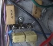
We've come to the conclusion that 5W is even better, but the largest non-wirewound
resistors commonly available are 3W so I plan to suggest a pair of 200 ohm 3W in
parallel, elevated above the board just above the metal heat sinks for the drivers.
If you turn up the amp with music those resistors will get very hot and that is what
it looks like happened there. Full oscillation causes smoke.
You have ceramic disk caps there - that's good since the poly caps melted.
That is the stereo version like the one I worked on as a kid, brings back memories.
For an amp that oscillates in mhz range under certain conditions, I would think a little self inductance from a wirewound resistor would be a good thing. We're not building radios here. I'm guessing these are the emitter resistors on the drivers?We've come to the conclusion that 5W is even better, but the largest non-wirewound
resistors commonly available are 3W so I plan to suggest a pair of 200 ohm 3W in
parallel.
That dingy RCR network around R12 R14 C3 C4 doesn't work to prevent oscillation, maybe it would be better do remove C3 C4 less they make a RLC oscillator with inductive emitter resistors.
SWTC was the amp kit price leader about 1975, he didn't dare spend $.05 more for resistors. I thought about buying one but saved up for a starter for my car and a recap tire instead. Walked to work a couple of months in 1975.
Last edited:
We've come to the conclusion that 5W is even better, but the largest non-wirewound
resistors commonly available are 3W so I plan to suggest a pair of 200 ohm 3W in
parallel, elevated above the board just above the metal heat sinks for the drivers.
If you turn up the amp with music those resistors will get very hot and that is what
it looks like happened there. Full oscillation causes smoke.
You have ceramic disk caps there - that's good since the poly caps melted.
That is the stereo version like the one I worked on as a kid, brings back memories.
Will be ordering a handful of 3W 200's right away and will be following this religiously for health tips for my two UT kids.
I've had a 207/a amp for many years that never had the least problem aside from the power supply caps finally going bad. Replaced a lot of carbon resistors with metal film and better quality electrolytics throughout and finally installed much faster MJ21193/94 devices with no apparent problems. Easily meets distortion specs. It's the only amplifier I've ever had with a CFP output stage.
However, that bias diode is mounted the same way. I ought to fix that.
However, that bias diode is mounted the same way. I ought to fix that.
For an amp that oscillates in mhz range under certain conditions, I would think a little self inductance from a wirewound resistor would be a good thing. We're not building radios here. I'm guessing these are the emitter resistors on the drivers?
That dingy RCR network around R12 R14 C3 C4 doesn't work to prevent oscillation, maybe it would be better do remove C3 C4 less they make a RLC oscillator with inductive emitter resistors.
SWTC was the amp kit price leader about 1975, he didn't dare spend $.05 more for resistors. I thought about buying one but saved up for a starter for my car and a recap tire instead. Walked to work a couple of months in 1975.
Hi Ian,
Sorry I missed this post, yes they are the driver emitter resistors and the associated
feedback resistors. You might be right about inductance helping but I want to keep it
similar to the original design for cases where people do not change the resistors. C3/4
drop the output stage gain to unity at HF and I doubt that they do much for stability.
I'm thinking that they might help to keep the output stage out of saturation by dropping
the gain at say 100KHz but I've not yet checked the -3dB frequency.
Looking for help with determining best options for replacing my SWTPC Universal Tiger two power supply caps.
Data on can:
Mallory Type FP
50 V 4000 uf
20-23892
235-7020Y 85c (7020 supposedly means 1970 year and 20th week of manufacture)
What's puzzling is when reading through one of Mallory's data sheets listing various types, it says that the FP with two solder terminals with D and ▽ next to them indicates a dual section cap but I was under the impression this had to be a single section 4000 uf cap.
Would be grateful if anyone can point me to a more recent vintage replacement cap that would have the same specs and footprint and if not possible, is rebuilding the caps a viable option?
Allen
Amps tend to burst into flames if poorly protected.
There should be a primary winding fuse before the mains switch and transformer.
There should be a fuse in each leg of the secondaries.
Some amps even have a fuse on the output.
If any of these are wrong value or missing the only outcome will be a disaster.
There should be a primary winding fuse before the mains switch and transformer.
There should be a fuse in each leg of the secondaries.
Some amps even have a fuse on the output.
If any of these are wrong value or missing the only outcome will be a disaster.
On the 207b schematic, F1, F2, & f3 are 3 amp fuses. F4 in series with the output is a 2.5 A slo blo. ?????
In response to abartee I would think a 3900 uf 63 or 80 v capacitor would be adequate. To adapt in snap in caps to these old boards, usually requires a transistion board of insulation. Strain reliefs holes for the wires keep them from being pulled around. I use NEMA CE material from mcmaster. 1/8" or 1/16". A 90 deg angle bracket of scrap metal with 2 holes can usually screw the adapter board down to some safe surface. I use #6 screws and elastic stop nuts so they don't come unscrewed.
There are a +40 and a -40 rail. If there are not two capacitors, then that is the explanation for the 2 section cap. Replace with two caps. Make sure - goes to the - rail and plus goes to the + rail. The two other terminals tie together and go to speaker ground.
Last edited:
Thanks for the replies. In further looking at the mallory terminal designations chart, the section with negative case was showing two terminals with half moon and triangle were two section duals but the section of the chart with floating case and two symbols is not a dual and triangle is negative.
The amp in question (stereo version of universal tiger) has two caps as in photo
The amp in question (stereo version of universal tiger) has two caps as in photo
Attachments
Well the green wire is obviously speaker ground. As to whether the half circle or the triangle is + or -, + goes to the emitters of the pnp output transistor and - goes to the emitters of the npn.
Well the green wire is obviously speaker ground. As to whether the half circle or the triangle is + or -, + goes to the emitters of the pnp output transistor and - goes to the emitters of the npn.
Sounds right to me. Pulled the fuses that were existing when I purchased the stereo version universal tiger amp (2S-175). For some reason I can't locate the mains fuse after pulling it a while back and didn't get a look at the amp rating! The other fuses are:
rectifier output = 5 amp
Left channel output = 5 amp
Right channel output = 5 amp
F1 mains fuse on the mono version with 62 volt secondary and 40 volt DC output is to be 2.5 amp slow-blo. Curios with this supply feeding two channels if the mains fuse would be double this value and be a 5 amp fuse?
The mono version used a 5 amp fuse on its speaker output fuse so I should be good there.
In an article linked to in one of the SWTC universal tiger threads, Dan Meyer calls the the Universal tiger a 125 W/ch stereo amp. 250 W from 120 vac is 2 1/4 amp, you double it for class AB inefficiency. He quotes in the parts list F1, a 5 amp normal blow (not slow blow) fuse. there is some confusion between F1 & F2, F2 is not slo blow, F1 is. F1 & F2 not on schematic. I'd use a 5 A slo blow for the mains fuse. Speaker fuse, those never work anyway, the output transistor always blows to protect the speaker fuse. Use a VI limiter for speaker protection, not a fuse. (VI limiter later invention, or if previous, not for the SWTC market which was alway the price leader).
Last edited:
- Home
- Amplifiers
- Solid State
- SWTPC Universal Tiger Rebuild For Analysis