This is a 300b SE amp I have been constantly tweaking and decided to try LED bias on the 6SN7 front end. I struggled to get more than 5mA and am shooting for 10mA.
I put a red LED in and I am reading 1.69V across it. These are experimental LEDs that I got from rat-shack and do not have a curve for them...
Most red LED curves I see put 1.7V right at about 10mA but how can I verify this with a no frills DMM?
The ear tells me that there is more frequency put through the speakers than before so subjectively I think that I have done a good thing. Eventually I would like to have some empirical evidence to support my observations...
Thanks!
Carl
I put a red LED in and I am reading 1.69V across it. These are experimental LEDs that I got from rat-shack and do not have a curve for them...
Most red LED curves I see put 1.7V right at about 10mA but how can I verify this with a no frills DMM?
The ear tells me that there is more frequency put through the speakers than before so subjectively I think that I have done a good thing. Eventually I would like to have some empirical evidence to support my observations...
An externally hosted image should be here but it was not working when we last tested it.
Thanks!
Carl
Last edited:
The whole point of using an LED is that its voltage hardly changes with current. So you have to do your measurement at the plate. What's the plate load and B+?
Use ohm's law with the 68k plate resistor. All the current through this resistor is also running through the first triode. Measure DC voltage across it, and the current is v/68, with the result directly in mA.
Good choice with the LED. Almost certain to be an improvement.
Good choice with the LED. Almost certain to be an improvement.
OK, looking at that circuit, you probably want more than 1.7V. I'd series two LEDs to give you 3.4V. 10mA is probably not going to be easy with resistor loads.
OK...
B+ = 403
B++ = 356
G1 = 0
P1 = 85
K1 = 1.69
G2 = 85
P2 = 258
K2 = 92
So, I measure 267 across the plate resistor - that is 267/68 = 3.9mA...
Interesting then it seems that 10mA is impossible...Starting to make sense...
I must say though...with the red LEDs there seems to be much more bass. I did also bypass the LEDs with the 2200uF caps...(nichicon UKWs...)
You should try it without the bypass caps as well and report your perception of the sound.
I have some data with and with out the bypass caps in a more exagerated example. I'll post the curves after you test and report back.
I have some data with and with out the bypass caps in a more exagerated example. I'll post the curves after you test and report back.
Ya, you will either need a higher B++ or else convert to CCS plate load to get 10 mA out of the SN7 with reasonable grid voltages.
Shouldn't be any need for a capacitor in parallel with the LED, if it's a decent LED.
Shouldn't be any need for a capacitor in parallel with the LED, if it's a decent LED.
To bypas the LED or not, that is the question.
The real answer is that it depends. There are pros and cons for doing so.
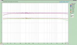
This is an exaggerated and not directly apples to apples comparison, but the attached shows the impact of bypassing a string of LEDS in the cathode. The Pink and Red are two sweeps with 660uF FC type and .1uFMKP bypass, the Brown and Green are without bypass caps. In this case it is a 12b4a and there are 7 LEDS in series.
I don't have a 6SN7 set-up otherwise I would repeat the experiment.
There is another BIG difference in that the 12b4 won't even come close to an overload condition as it is biased around 17Volts. (at least the way I am using it) The 6SN7 may.
The real answer is that it depends. There are pros and cons for doing so.
This is an exaggerated and not directly apples to apples comparison, but the attached shows the impact of bypassing a string of LEDS in the cathode. The Pink and Red are two sweeps with 660uF FC type and .1uFMKP bypass, the Brown and Green are without bypass caps. In this case it is a 12b4a and there are 7 LEDS in series.
I don't have a 6SN7 set-up otherwise I would repeat the experiment.
There is another BIG difference in that the 12b4 won't even come close to an overload condition as it is biased around 17Volts. (at least the way I am using it) The 6SN7 may.
Attachments
Can an LED go on top of a 140 VDC negative rail to the cathode of an LTP? In this case, it's a 6SL7 biased at 1.8 VDC and drawing about 2 ma.
Thanks,
Thanks,
Yes, but why would you want to? You might need -12V max, depending. The rest is essentially thrown away as heat and power usage.
Thanks, I really appreciate the quick reply
I'm still struggling with non-resistor loads, i.e. LEDs and CCSs. That "depending" concerns me a little, but I can certainly come up with a -12 to check things out. The original -140 gave me a pretty long tail and has worked well, but I'm interested in alternative approaches. What I still don't understand is how to arrive at that -12. Ah well, another day.
I'm still struggling with non-resistor loads, i.e. LEDs and CCSs. That "depending" concerns me a little, but I can certainly come up with a -12 to check things out. The original -140 gave me a pretty long tail and has worked well, but I'm interested in alternative approaches. What I still don't understand is how to arrive at that -12. Ah well, another day.
It's easy. First, you need enough voltage across the CCS so that it's working. 10V is enough for nearly any CCS made of silicon- bipolar or MOSFET. Second, you need enough voltage so that the signal doesn't go below that minimum- for an LTP, that's one-half the input voltage. For a 2V input sensitivity (common these days), which is 2.8V peak, that's 1.4V, for a grand total of 11.4V. I rounded to 12V just because that's an easy voltage to come up with.
You could even shave a volt or two off that, if you needed, since I ignored the extra 1.5V or so of bias on the 6SL7. -9V would probably work just as well. CCS are really, really cool circuit elements.
You could even shave a volt or two off that, if you needed, since I ignored the extra 1.5V or so of bias on the 6SL7. -9V would probably work just as well. CCS are really, really cool circuit elements.
Thanks again Stuart,
Can't get much more clear or concise than that.
School's out for the season everywhere but here.
Can't get much more clear or concise than that.
School's out for the season everywhere but here.
- Status
- Not open for further replies.
- Home
- Amplifiers
- Tubes / Valves
- Switched to LED bias on 6SN7 cathode - how do I calculate current?