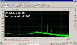
Is there an explanation for the poor performance of the LM4562? The LM4562 should at least be better than the NE5532 at THD. I'm disappointed.
Attachments
Based on some feedback in the TI forums from a few users, it seemed there was an issue with the LM4562 starting in recent years. First it was noise problems. And yes, it should outperform the 5532 in noise, distortion and drive capability.
I’d love to find that discussion and the measurements, but, being in Canada, I only now get a fraction of the search engine results I used to get.
I’d love to find that discussion and the measurements, but, being in Canada, I only now get a fraction of the search engine results I used to get.

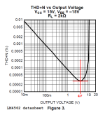
All tests were done at 3 Vrms. But even that doesn't matter much because it's a comparison. The others do better.It might be illuminating to re-test the LM4562 with an output signal magnitude of 2.828V RMS, which is 8.00V peak-to-trough. Peaks are at +4.00V and troughs are at -4.00V.
_
Based on some feedback in the TI forums from a few users, it seemed there was an issue with the LM4562 starting in recent years. First it was noise problems. And yes, it should outperform the 5532 in noise, distortion and drive capability.
I’d love to find that discussion and the measurements, but, being in Canada, I only now get a fraction of the search engine results I used to get.
This refers to low freq. noise. Another problem of the LM.
https://e2e.ti.com/support/audio-gr...um/415907/lm4562-lme49720-low-frequency-noise
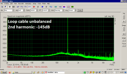
Distortion at this low level can be masked by poor ground layout injecting non-linear signals into the wrong places, or other such subtleties - is the first plot the loop-back measurement?
Are all the measurements balanced?
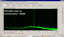
-136dB for 2.8V signal is less than 500nV error which can be caused by a mere 500µA of rail noise flowing through 1 milliohm of ground trace in the wrong place. The opamp output and supply signal currents will be about 5 times this, and the supply currents are half-cycles so very non-linear.
Unless using groundplane ground traces are more likely to be 10's of milliohms to 100's of milliohms, not 1 milliohm, so its vital to use careful star grounding layout and ensure non-linear current paths do not create IR voltages visible at the input or output grounds.
Try changing the 1k load to 2k - if the distortion drops 6dB it may be non-linear currents.
[ BTW you must use a flattop window for the FFT if you want to make accurate measurements of spectral peaks, The Hann window has several dB of scalloping error ]
[[ one more thought - the LM4562 is more sensitive to RFI than many chips, do your experiment in a Faraday cage if you can - the OPA1656 is FET and will be robust to RFI ]]
Are all the measurements balanced?
-136dB for 2.8V signal is less than 500nV error which can be caused by a mere 500µA of rail noise flowing through 1 milliohm of ground trace in the wrong place. The opamp output and supply signal currents will be about 5 times this, and the supply currents are half-cycles so very non-linear.
Unless using groundplane ground traces are more likely to be 10's of milliohms to 100's of milliohms, not 1 milliohm, so its vital to use careful star grounding layout and ensure non-linear current paths do not create IR voltages visible at the input or output grounds.
Try changing the 1k load to 2k - if the distortion drops 6dB it may be non-linear currents.
[ BTW you must use a flattop window for the FFT if you want to make accurate measurements of spectral peaks, The Hann window has several dB of scalloping error ]
[[ one more thought - the LM4562 is more sensitive to RFI than many chips, do your experiment in a Faraday cage if you can - the OPA1656 is FET and will be robust to RFI ]]
Last edited:
More about LM4562 in a couple of threads:
https://www.audiosciencereview.com/...d-signal-with-1mhz-carrier.20828/#post-689704
https://www.audiosciencereview.com/...the-lm4562-lme497x0-family.10687/#post-296533
https://www.audiosciencereview.com/...d-signal-with-1mhz-carrier.20828/#post-689704
https://www.audiosciencereview.com/...the-lm4562-lme497x0-family.10687/#post-296533
I stumbled upon this thread after a circuit I designed and tried with an LM4562 was making odd noises. Of course, I could see it on my QA401 analyzer as well. I discovered that the problem was the WiFi router/internet gateway device maybe 1.5 meters away. The TI NE5532 I had originally designed the circuit with would react if I put myself in just the right place. I then got out my Uniden DECT 6.0 cordless phone and started trying other chips. With the dual bipolar op-amps that I tried, the National version both old and current production LM833 behaved the best. An old 1982 Signetics NE5532 was the same as the current TI part, placing the handset about 1 meter away got into the NE5532s. So, as bipolar duals went for this crude test, from best to worst, LM833, NJM2068, ST's MC33078, OP275, On Semi NE5532, OPA2227, TI/Signetics NE5532, and a distant last place LM4562. The JFET TL072 and OPA2134 didn't react. I then tried a bunch of single op-amps in a different board as I have some LME49710s. Again the LME49710 performed poorly. To verify my test layout was okay, I also tried (with different feedback resistors) an AD844 current feedback type. There was no oscillation. I then tried a AD847 and AD797, still stable. The AD797 barely reacted the the DECT phone and the AD844 and AD847 behaved better than the NOS Signetics NE5534A I tried. An old LF351 didn't react at all until I got the phone handset within 10cm or so, then it kind of abruptly caused a small amount of interference. I then tried an old SGS-Thomson LM318. It was consumed by the fact there's a 50kW AM station 3-4 kilometers away from me at 680kHz... The last were the LM301A's. I wanted to try these since I had one in a metal can. Surprisingly, the metal can behaved as bad as the LME49710. The plastic very old 14 pin DIP one was better. So, singles best to worst, AD797, LF351, AD844, AD847, LM301A 14DIP, NE5534A, LM301A metal can, LME49710. My crude test kid of shares what the person at Audio Science Review and https://proaudiodesignforum.com/forum/php/viewtopic.php?f=6&t=939 found. That said, if there's not strong WiFi/DECT RF nearby my measurements agree with published datasheet specs for noise.
It's interesting to note the NE5532 was more susceptible than I thought it would be. 20years+ professionally, I've worked around high power transmitting equipment with plenty NE5532's nearby passing audio. Commercial AM/FM frequencies don't seem to bother much but the LM318, and the LM318 is fairly popular for FM composite audio use, but I've only seen the National or TI versions, here.
One idea to try, SMD, and maybe some 10pF chip caps from out to ground, + in to ground and between the +/- input pins and of course, proper decoupling. Obviously a different part is easier, but let's say for now "challenge accepted"...
I hope this was worth sharing my recent experiences. It got me going on quite the tangent. (I guess if I don't go off on sine or cosine, I'll be okay)
Its usually a great idea to use an all metal enclosure and add RF ingress protection (ceramic caps on the inputs at the connectors, 100 to 500pF sort of value). Commercial products are tested for RF/MW susceptibility and usually this sort of thing gets caught.
Adding small caps to opamp inputs is risky, you might turn it into an oscillator. Best to shield the whole circuit, RF and microwaves inside a box bounce around all over the place in unpredicatable ways. At microwave frequencies in particular PCB traces can be tuned resonators inadvertently.
Adding small caps to opamp inputs is risky, you might turn it into an oscillator. Best to shield the whole circuit, RF and microwaves inside a box bounce around all over the place in unpredicatable ways. At microwave frequencies in particular PCB traces can be tuned resonators inadvertently.
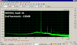
That graph for the NE5532 shows an amount of THD that is easily an order of magnitude lower than anything mentioned an any 5532 datasheet I have seen. I wonder why that is---???
Also, for audio use, I see no benefit to having FR out to 10 MegaHz. I always put 100 nF COGs right at the opamp between the power pins 4 and 8, and I put 22pF caps across any feedback resistors. This limits the FR to ~ 200KHz, which is more than enough for audio and rids the tendency to oscillate and/or be affected by nearby MHz devices. I would value a measurement of your devices with these components in place.
Also, for audio use, I see no benefit to having FR out to 10 MegaHz. I always put 100 nF COGs right at the opamp between the power pins 4 and 8, and I put 22pF caps across any feedback resistors. This limits the FR to ~ 200KHz, which is more than enough for audio and rids the tendency to oscillate and/or be affected by nearby MHz devices. I would value a measurement of your devices with these components in place.
Thanks for this ss2222a.I discovered that the problem was the WiFi router/internet gateway device maybe 1.5 meters away. The TI NE5532 I had originally designed the circuit with would react if I put myself in just the right place ....
My experience is also that LM4562 and some other uber OPAs are poor and OPA2134 is good for RFI
My $0.02 is that the earthing and decoupling arrangement has a HUGE effect on THD bla bla too. My favourite method is 2x10u electrolytics from each rail to earth AT the device. Once you have these in place, you can add anything else you like but performance won't get better ... But don't leave out my electrolytics!
Kingston has a HUGE thread on what is REALLY important for noise & THD; opamps and local decoupling of rails, some questions
http://www.groupdiy.com/index.php?topic=37307.80
Many true gurus (and some pseudo gurus) chime in. It proves how OPA rolling takes a VERY poor second place to correct earthing, layout & decoupling. It’s a long thread but read the whole thing from #41 to find pearls of wisdom.
"Also, for audio use, I see no benefit to having [opamp frequency response] out to 10 MegaHz"
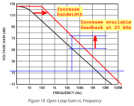
A lot of people want this because they want to maximize the amount of feedback available at the top of the audio band, 20 kHz. More feedback means more "error correction" / distortion reduction. Which means lower distortion. Which is their goal.
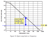
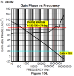
They print out the opamp datasheet's open loop frequency response plot, draw a horizontal line at the gain value they have chosen for their circuit (example: a linestage designer might choose a gain value of +12dB {equals 4.0 volts per volt}) and then measure the vertical distance between the just-drawn horizontal line, and the opamp's open loop frequency response ---> at 20 kHz <--- . This is the amount of feedback available.
One easy way to increase this vertical distance, is to shift the entire frequency response plot to the right. Namely: to increase bandwidth. Then you get lower distortion, and lower is automatically better.
A lot of people believe this. Not everyone, of course; but a lot.
Another, not so easy, way to increase the vertical distance (available feedback) even further, is two pole compensation. See the datasheet of the externally compensated LM101 for examples. Also the National Semiconductor Linear Brief named LB-4 ("snoa679"). Both Cordell and Self discuss two pole compensation, in their textbooks on audio power amplifiers.
_
A lot of people want this because they want to maximize the amount of feedback available at the top of the audio band, 20 kHz. More feedback means more "error correction" / distortion reduction. Which means lower distortion. Which is their goal.
They print out the opamp datasheet's open loop frequency response plot, draw a horizontal line at the gain value they have chosen for their circuit (example: a linestage designer might choose a gain value of +12dB {equals 4.0 volts per volt}) and then measure the vertical distance between the just-drawn horizontal line, and the opamp's open loop frequency response ---> at 20 kHz <--- . This is the amount of feedback available.
One easy way to increase this vertical distance, is to shift the entire frequency response plot to the right. Namely: to increase bandwidth. Then you get lower distortion, and lower is automatically better.
A lot of people believe this. Not everyone, of course; but a lot.
Another, not so easy, way to increase the vertical distance (available feedback) even further, is two pole compensation. See the datasheet of the externally compensated LM101 for examples. Also the National Semiconductor Linear Brief named LB-4 ("snoa679"). Both Cordell and Self discuss two pole compensation, in their textbooks on audio power amplifiers.
_
Attachments

Last edited:
Surely this is just saying the circuit FR should have a roofing filter? Nothing contraversial there. i.e. its a statement about closed loop FR, not opamp compensation or open-loop gain.Also, for audio use, I see no benefit to having FR out to 10 MegaHz. I always put 100 nF COGs right at the opamp between the power pins 4 and 8, and I put 22pF caps across any feedback resistors. This limits the FR to ~ 200KHz
I am sure that everybody noticed: the available feedback at BASS frequencies is enormous!! Tremendous amounts of feedback, thus tremendous amounts of error correction, thus tremendously reduced distortion. Vanishingly small distortion. Negligibly small distortion.
Which means: opamp based linestages have NO DISTORTION in the bass. They're all perfect and therefore they must all sound the same in the bass. All opamp based linestages have the same bass.
And that's what listeners hear, isn't it? All opamp based linestages sound the same in the bass? Or is there some kind of flaw in the "available feedback is nirvana" concept?
_
Attachments
Last edited:
As long as the charging capacitors are not drained.Which means: opamp based linestages have NO DISTORTION in the bass.
Many opamps have only ~90--100dB of open loop gain (when loaded), which will limit performance across the spectrum
Consider 30dB closed loop gain with a 100dB gain opamp, there's only 70dB to linearize the system, so performance can be limited unless the open-loop is pretty linear to start with. The NE5534/5532 falls in this category, but seems to use multiple internal feedback loops to improve open-loop performance (part of its secret sauce together with low current noise inputs). Output biasing to put the chip into class A is one trick for improvement when the open loop gain is low.
High performance audio opamps can have as much as 140dB open loop gain, under a full 600 ohm load... The LM4562 is an example. The open loop linearity is much less important when you have this much gain, but stability/compensation are probably trickier.
- Home
- Source & Line
- Analog Line Level
- Surprising op amp measurements