TA2022
Hi Dweekie,
That depends on demand, if people are interested
ill buy those in bulk too, but these are more expensive than the TA2024.
The price indication is around 45 euro per board.
if i can buy more boards, maybe that could be a bit less.My chinese negociation skills will be tested...
needless to say, im not going to buy 100 boards in the hope that there are 100 customers. this could be like a group buy thing.
Greetings,
Arjen

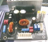
TA2022
These are the specs for the TA2022 PCBA.
Size, 95 MM-68 MM high 50 MM (with heat sink)
Power requirements,
5 volts 500mA ~ 1 A and + 20V & - 20V 4~10 A
So a 40 volts transformer with middle line will do fine.
FEATURES
Class-T architecture
High Power
100W @ 4Ù, 1.0% THD+N
90W @ 4Ù, 0.1% THD+N
60W @ 8Ù, 0.1% THD+N
“Audiophile” Sound Quality
0.015% THD+N @ 70W 4Ù
0.015% THD+N @ 45W 8Ù
0.10% IHF-IM @ 25W 4Ù
High Efficiency
92% @ 88W 8Ù
87% @ 125W 4Ù
Dynamic Range = 102 dB
Mute Input
Integrated Gate Drive Supply
Over-current protection
Over and under-voltage protection
Single ended outputs
Outputs can be operated in bridged mode
at www.datasheet4u.com you can find the datasheet for this IC.
Attachments
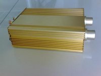
guts
ill show you guys the guts later, i had no time to unscrew it this morning i was already getting late for work 😉
ill show you guys the guts later, i had no time to unscrew it this morning i was already getting late for work 😉
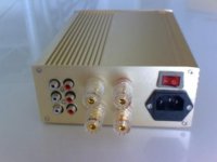
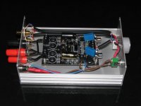
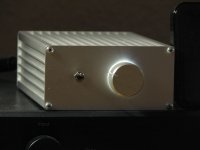
Got Guts!
Well then, here the photo's of the inside of my little T
its not really 100% good... next one i will put the caps in a better place, maybe even put the PCB vertical, why not?, then i can put those 10 000 uF Rubicon caps in there.
The powersupply is a switching 12 V 2 A supply, ive got a fuse in the connector, 1 A and in the powersupply, 1 A
Power switch is on the back, and ive found small cute VU meters, 2CM in diameter but i still need to make a small circuit with op-amps to feed those, so perhaps on the next one, also VU meters.
Attachments
KITS
Yeah, that could be done, i guess.
Its not so very very cheap to make this amplifier, its all together around 300 ~ 350 RMB
Especially because of the alps pot meter, and the housing, and the fact that everything is the best quality i could fins here in the open market.
if i could make 100 PCS, that would be a different story! different prices all around
ive also seen some nicer housings in the market here, but then your talking about 17 ~ 25 euro. but very nice, thick slab of aluminium at the front, switch and volume knob included, and connectors at the back included.
but those are heavy and shipping cost might cause trouble...
kits
being a complete newby, I am attracted to getting all the pieces including proven tweaks in one box.
As it is now, I pay shipping on every pot, cap, speaker connect and power supply.
As soon as I order a few bits I find another post recommending a different capacitor or different K pot. It's a pain being so clueless but I guess that 's how you learn. .... And maybe I don't want it to be easy.
Tweakers
Hehe Tilroh, dont over estimate the Tweakers.
if you have 100 engineers, making the same thing you will end up with 100 totally different " best possible solutions"
thats the fun about the hobby here, everyone does it different.
so i suggest you keep tinkering with it until You are happy!
afterall, its made to please your ears, in your living room.
other tweakers have different speakers, different living room and different ears that listen to different music...
so there is no one solution. thank god for that! so now we have 1000's of different solutions to talk about, argue about and laugh about
Arjen, in your little T you didn't alter the coupling caps, did you?
Has anyone so far taken the effort to draw the schematic of Arjen's board?
I can see that R2 and R4 are the input resistors and R5 and R6 are the feedback resistors (all 20k)
What values are C24_2 and C23_2 on the bottom of the board? They are parallel to each input channel. Has anyone tried to remove them?
Three of the four channels I own (2 boards) have very low output voltage, but one comes at 105mV. Can this be tolerances or should I go hunting for other effects (stray solder or so)?
thanks for any hints
Hi there Mr Fishy,
Nope, those caps are as they came, one 250V MKP 1uF and 1uF electrolytic piggy backed.
I have not been messing around with it too much, but i did see that of all PCB's one channel had a way too high DC output.
So i have re-worked all PCB's by connecting C28 to the negative output to solve this problem. if you have one channel with too much DC, perhaps you can add a 10nF cap over the out put or over one of the outputs to ground.
you can let me know your findings!
Greetings,
Arjen
oh, so that solder blob at the end of c28 was you!
I was wondering what piece of quality assurance I was witnessing here...
Again, a circuit diagram would come handy.
I is precisely the channel with the blob that shows over 100mV, but only on one board.
What would a small cap do to a DC voltage?
I can try but I first have to pick up some components, I don't have small caps in the box right now.
Wrt the input caps, I remember you writing that the ESR of the 'lytics wasn't favorable. And in a picture of a different amp you posted the 'lytics were gone. Any findings on audible differences?
Cheers.
input caps and so
Hey hey
Yeah i had to rework 100 boards, but quality first hey!
the input caps i have not payed with much, the MKP has 0.5 Ohms ESR the lyitcs have 6 ohms or so, poor quality.
so today i picked up a bunch of fake audiophiler 2.2 uF 400V caps. for 80 cents a pop.. ill hook them to the HP capacitor meter and see if there any good.
The caps have kondensotor written on them... hahahah
dosnt mean that there very bad neccesairily but ill find out monday!
ill try it and let you know later
Greetings,
Arjen
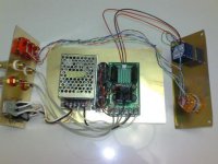
Et voilà
Here it is, my first DIY-Amp: 😎
It uses a sure board. I ordered it ages ago, but the first shipment was lost. Sure was nice enough to send a second one that made it through.
Mods are a selection from those proposed in this thread:
- removed C3, C24
- replaced C13, C21 with EPCOS 2.2 uF MKT caps
- removed R3, R16 which lowered offset to 5 and 50mV
- replaced R8, R14 with 10k
- added Panasonic FM
- 220 uF parallel to C9, C19
- 2200 uF parallel to C27, C31
It is powered by an IBM notebook SMPS rated 16V, 3.36A. It actually delivers 16.5 which I bring down by about a Volt by running it through two diodes.
Volume control is needed and I use a vishay P9A 10k "log" pot. Works quite well, methinks.
I would be interested in adding a buffer, but I wouldn't want to compromise the simplicity of the setup. That is, I'd be grateful to learn of a buffer design that can run from a 15V non-symmetric power supply so it can go in this box.
Currently the little comrade gets some exercise - I am amazed how well it plays.
Attachments
- Status
- Not open for further replies.
- Home
- Amplifiers
- Class D
- Sure Electronics Tripath boards?