Zigis
you can reduce the gain by using slightly smaller values for R7/R13
Tilroh and Pincellone:
In fact, only a buffer (look in the gainclone area for smart buffers) is a good solution to get proper volume control in front of a TA2024.
Replacing R7/R13 by a poti does not seem to be a good solution. I dont know if the input-opamps are working stable with unity gain or lower!
And you will apply a lot of feedback for "normal" volume levels.
Regards
Franz
Arjen,
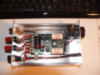
As advised the boards arrived very quickly, thanks again.
Have built 1 up with Mundorf M Cap's on the input's & a 4700 uF low ESR across the DC input, but directly coupled to the existing Tanik caps.
Will give it a bit of a burn in then do an evaluation on some decent speakers / source.
Will report again once this has been done.
Paul
Attachments
Tripath PCB's
That looks cool paul! hope it sounds as good as it looks!
please let me know your findings, and conciddering the groundplane is not very big, it might be a good idea to glue a little strip of aluminium to the top of the IC.
When i connect my big 4 Ohm speakers to it it gets a bit to hot. but with 5 CM of alu on its head there's no problem.
Greetings,
Arjen
ZL2BPS, are you measuring DC offset?
With Sure boards there is problems, maybe Arjen's boards is better ?
Zigis.
With Sure boards there is problems, maybe Arjen's boards is better ?
Zigis.
Arjen,
Listening to Diana Krall on it now & it's mellowed considerably with 12 hours on it. It was a bit sibilant to start with as was my Sonic Impact when 1st modded.
Plenty of bass for me (Tried it on a digital recording, Bach, Tocatta & Fugue in D minor, from De Bevenkerk Kempen in your home country. ) & seems to have a reasonable soundstage from what I can judge out here in the shack.
Will see how in sounds with another 24 hours on it & then take it into the house & connect it up to a pair of AR's.
After running for 12 hours on 8 Ohm speakers I could not feel any heat on the chip, but that was at low output. Yes I have made up a H/S but need to get some heat conductive glue to stick it down.
When I get some time I will sit down & try & draw up the circuit to see how it compares with the Tripath evaluation board. Have you looked at that aspect.??
Paul
Arjen's boards will be better because they don't have the 'messed- up' DC correction circuit on the inputs😀
I don't know why sure still have that in place when they don't even put the correct resistor values in there to make it work😕
I don't know why sure still have that in place when they don't even put the correct resistor values in there to make it work😕
Zigis.
I have only ever had 1 x sure board that did not come acceptably low after removal of R3 & R 16.
That board is by memory round 35/140 & is sitting here to mod at some stage.. All other's have been in the 30's > 40's mV. Some, ( 1 or possibly 2 ) did not require removal of R3 & R16.
I did read somewhere in Tripath data that " DC offset, Typical 50, Max 150, mV. " I think it was the TA 2020 Data sheet. My feeling is that 150 is high but dont think I would worry about 70mV too much.
You can always modify it with an on board trimmer.
OK Arjens boards were: 30/30, ( the board I am listening to now ) & the 3 others were 77/49, 22/15, & 40/48 mV.
Paul
Franz Gysi said:Zigis
you can reduce the gain by using slightly smaller values for R7/R13
Tilroh and Pincellone:
In fact, only a buffer (look in the gainclone area for smart buffers) is a good solution to get proper volume control in front of a TA2024.
Replacing R7/R13 by a poti does not seem to be a good solution. I dont know if the input-opamps are working stable with unity gain or lower!
And you will apply a lot of feedback for "normal" volume levels.
Regards
Franz
Franz,
would a preamp like this one solve the problem?
http://www.futuraelettronica.net/pdf_ita/8220-K8084.pdf
It's a Velleman Kit, perhaps I could also use better components.
I'm also considering this one, which uses a specific IC from Philips and linear pots, although it seems to have lower specs
http://www.quasarelectronics.com/3100.htm
Any advice is very welcome!
Thanks
Al
Hi Al
personally I dont like tone controls, as I think, they mess up the sound.
No, I think keep it simple:
Maybe a good poti for volume control, input caps followed by a good opamp in unity gain, dc coupled to the t-amp would be a easy and small solution.
Or a tube, a cathode follower.
Or a FET buffer (look at Pedja Rogic's Gainclone buffer).
Kind regards
Franz
Zigis.
Found the data sheet for the TA-2024c I was mentioning last nite wherin the problem is discussed on pages 11>13 & 3 methods of fixing it. ( obviously based on the EB-TA2024 board )
Have a look at: http://pdf1.alldatasheet.com/datasheet-pdf/view/143080/TRIPATH/TA2024C.html
I dont really believe that 150mV is acceptable as they would imply. Now I have found this I may fix my board with a 140mV offset on 1 channel..
Hope this is of some use as you cannot get this data off tripath any more, their site being closed down.
regards
Paul
Zigis
Thanks for making me aware of this nice prints!
What I am actually building:
A little desktop amp for my computer, to drive the Fostex FE83E in the recommended enclosure.
The enclosure of this amp was a Studer Talkback box. For volume control I have a stepped 10k attenuator.
During building I realized the fact of needing a buffer.
I will think about available space in the box and tell you later the results.
Maybe after my vacation, coming soon...
Regards
Franz
/Edit:
Did you see this fine buffer:
http://www.diyaudio.com/forums/showthread.php?s=&threadid=116193&perpage=25&pagenumber=1
Maybe not for my desktop amp, but it could be a very interesting solution!
Thanks for making me aware of this nice prints!
What I am actually building:
An externally hosted image should be here but it was not working when we last tested it.
An externally hosted image should be here but it was not working when we last tested it.
A little desktop amp for my computer, to drive the Fostex FE83E in the recommended enclosure.
The enclosure of this amp was a Studer Talkback box. For volume control I have a stepped 10k attenuator.
During building I realized the fact of needing a buffer.
I will think about available space in the box and tell you later the results.
Maybe after my vacation, coming soon...
Regards
Franz
/Edit:
Did you see this fine buffer:
http://www.diyaudio.com/forums/showthread.php?s=&threadid=116193&perpage=25&pagenumber=1
Maybe not for my desktop amp, but it could be a very interesting solution!
Hehe.. thats my thread. By coincidence I have 5 of these tripath boards sitting in my big cardboard box of Sure goodness. I will be using this buffer with the sure amps
I'm sending the files off this week for printing.
I'm sending the files off this week for printing.
Franz Gysi said:Hi Al
personally I dont like tone controls, as I think, they mess up the sound.
No, I think keep it simple:
Maybe a good poti for volume control, input caps followed by a good opamp in unity gain, dc coupled to the t-amp would be a easy and small solution.
Or a tube, a cathode follower.
Or a FET buffer (look at Pedja Rogic's Gainclone buffer).
Kind regards
Franz
Perhaps I found what I was looking for...
How about this one?
http://cgi.ebay.it/NE5532-HI-FI-STE...12050QQcmdZViewItemQQ_trksidZp1713.m153.l1262
Because you can also use single opamps if you like (such as OPA627BP). NE5532 is dual and comes along with the board.
I will probably use it with LME49720
I will probably use it with LME49720
Yes, this could be suitable.
But you have to reduce the gain from +20dB to unity gain by replacing the feedback resistor.
Maybe from the same vendor the FET buffer is better for this application?
You may have a look at item # 120230964247 in eBay.
Franz
But you have to reduce the gain from +20dB to unity gain by replacing the feedback resistor.
Maybe from the same vendor the FET buffer is better for this application?
You may have a look at item # 120230964247 in eBay.
Franz
Franz Gysi said:Yes, this could be suitable.
But you have to reduce the gain from +20dB to unity gain by replacing the feedback resistor.
Maybe from the same vendor the FET buffer is better for this application?
You may have a look at item # 120230964247 in eBay.
Franz
Thanks Franz, but I'm not that expert. You probably mean that I should change the resistors lying beside the capacitors with some others, in order to decrease the gain isn't that right?
Or maybe you mean that I should reach a gain of 1 (the very same of the input, so no gain at all).
Consider that from the picture I read that the board takes 18v but I will power it up with 13.8V as I plan to put it inside the very same case of the amp.
Can you please let me know if I pointed out the correct position of the resistors and what would be the ideal value for them?
How about using some trimmers instead?
I know that some opamps are "unity gain stable" and some others are not, although I didn't really understand what that means

I've already ordered the board. I also considered the FET buffers but I was not too sure about how to connect a pot between the source and their inputs, so I went for the opamps board instead...
Al
I know that some opamps are "unity gain stable" and some others are not, although I didn't really understand what that means
Its what it says on the tin...
Some opamps are quite happy to work at a gain of 1, (good times) others require a minimum amount of gain or else they become unstable and oscillate (bad times)
The datasheet or manufactures web page will normally tell you wether they are in the opening preamble.
Quite often there will be two similar opamps one Unity gain stable and another non-unity gain stable for example the OPA627 (stable) and the OPA637 (not so)
From memory the 5532 is stable at gain1, but I would check before relying on my memory
While waiting for some answers (from Franz or any other skilled mind) about getting unity gain, I've found this:
A unity gain buffer amplifier may be constructed very simply by connecting the output of an operational amplifier to its inverting input (negative feedback), and connecting a signal source to the non-inverting input. For this circuit, Vout is simply equal to Vin.
The importance of this circuit does not come from any change in voltage, but from the input and output impedances of the op-amp. The input impedance of the op-amp is very high (MÙ to 10 TÙ), meaning that the input of the op-amp does not load down the source or draw any current from it. Because the output impedance of the op-amp is very low, it drives the load as if it were a perfect voltage source. Both the connections to and from the buffer are therefore bridging connections, which reduce power consumption in the source, distortion from overloading, crosstalk and other electromagnetic interference.
So I wonder if I just need to short some of the opamp's pins to make a unity gain buffer amp...
http://en.wikipedia.org/wiki/Buffer_amplifier
Anybody?
Hello
Sorry, I thought, you have the answer from Blair.
Indeed, you are on the right track. Just study the base opamp circuits and then identify the circuit from the board you purchased.
I think, it is a non inverting circuit, like showed in this link:
http://ourworld.compuserve.com/homepages/Bill_Bowden/opamp.htm
So, when you set RA = RB then you will get a gain factor two. This could work.
BTW: I am not a developping engineer...
Kind regards
Franz
- Status
- Not open for further replies.
- Home
- Amplifiers
- Class D
- Sure Electronics Tripath boards?