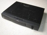
And this is the exterior of the box.
PS. Thank you to all of you, from the questioners to the advisers. Reading through these posts have inspired me to build three of these units for use around the house. Special thank to Paul (you know whom you are) who helped me through these fun projects.
PS. Thank you to all of you, from the questioners to the advisers. Reading through these posts have inspired me to build three of these units for use around the house. Special thank to Paul (you know whom you are) who helped me through these fun projects.
Attachments
Very nice Cheric. I love the big Obbligato caps. The picture makes them look tiny. That's an impressive first project.
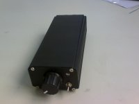
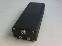
Very Portable HIFI
I had an idea last time when i was at the beach listning to my micro speakers ( Class D 2X2 watt Eutech IC )
I thought, this can be better, but it should still be a small efficient amplifier as it will be battery powered.
So i went to the market and bought a small black housing and tried to fit one of my TA2024 PCB's in there
Ofcource, it didnt fit hehe so i had to remove 1 MM of PCB at both sides to make it fit
Also bought 3 X 3.7 volts 1000mA polymer cells and a protection PCB for charge and distcharge protection.
so 12 volts all together to power the PCB, 2 3.5 mm Connections, one input, one output simple switch on the front side, and a blue LED above the power switch.
The result is a light weight durable and well sounding ampifier
now i need to design and make some speakers, i aready have 2 5 watt speakers that look very nice, with rare earth magnets and a very nice suspention.... ill keep you guy's posted!
Attachments
Could you tell me the maximum voltage of the fully charged polymer batteries? I've been wanting to try them for a while.
dweekie said:Could you tell me the maximum voltage of the fully charged polymer batteries? I've been wanting to try them for a while.
4.2v I think...
Arjen: Put me down for 4 tripath boards.
I'll send you an e-mail. 🙂
Hi Arjen,
I may order some boards (although I have a large backlog of PCBs and kits yet to finish and task!) but how about selling on some of those cases and knobs? It seems to be hard to find good-looking cheap ones in the UK
Chris
I may order some boards (although I have a large backlog of PCBs and kits yet to finish and task!) but how about selling on some of those cases and knobs? It seems to be hard to find good-looking cheap ones in the UK
Chris
audio1st said:Nice work Bongoman..
You should try some better input and feedback resistors, seem to make a difference with top end sparkle.
I've teamed mine up with a 12V , 6A power supply, also from SURE , turned up to 13.5V (so far)...
I have removed the second stage of the output filter and put a single cap across the speaker terminals at the moment, (haven't listened yet)
I really like these boards...

Audio1st
I know this is a newbie question, but I am... 😀
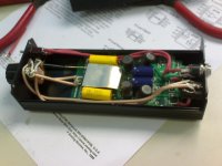
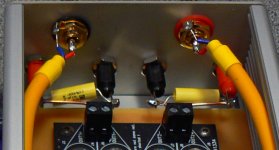
I noticed that you put 3 large yellow capacitors in the speaker connectors and there is a blue cable connected on the right hand side of the box for ground.
Can you please let me know why those capacitors are needed, what values should I pick and where to connect them it's not easy to see this in the picture you provided, I barely see the connections and I'm not sure.
As you are not using a pot, do you need a preamp to use the amp?
Where should I connect the ground cable?
Please don't laugh... Thanks!
Pincellone wrote: Is there anybody that could answer me?
Well I tried to find the photo you were refering to but couldn't What post No. Was it in ??
Will try & answer if I can find the photo, but not till tomorrow as it''s 1:30 am here.
Paul
Well I tried to find the photo you were refering to but couldn't What post No. Was it in ??
Will try & answer if I can find the photo, but not till tomorrow as it''s 1:30 am here.
Paul
I appreciate that...
Here is the link:
http://www.diyaudio.com/forums/attachment.php?s=&postid=1390930&stamp=1199449122
Here is the link:
http://www.diyaudio.com/forums/attachment.php?s=&postid=1390930&stamp=1199449122
Pincellone.
OK Got The link you sent & as you are getting no reply here's my interpretation.
I can only see 1 yellow Cap across each speaker terminal. Total of 2 not 3. Most people I think don't fit them & I assume he has fitted them to drain off some of the RF getting through from the chip. I certainly did not add these but may try & locate some suitable quality cap's & give it a whirl.
Sonic Impact use .1 > .15 uF across the output terminals but I don't know what the Sure has further "upstream" in the output filter. If you want to experiment, try something round the above values.
Re Pot/Preamp. You need some way of controlling the Vol, unless like me you live on a farm.
If you feed it from line out you will need a vol pot or Preamp.
If you feed it from a "headphone socket"you will be able to control the Vol from your source device. Ipod, walkman etc.
Re Ground Wire. I cannot see where he has run it to either but it's seemingly terminated on a bolt holding both cases together & his P/S output looks to run directly with + & - leads to the board screw socket.
I grounded mine as follows.
Shielded input's from RCA's at both ends, to case @ RCA end & at pot end to a lug on the board standoff hole. Wiring from Pot sweeper to board uses the new input caps for + and shielded cable for -'s grounded to another lug.
Hope that's some help & if anyone disagrees please feel free to add your input.
Paul
Thank you very much for your reply Paul.
There is something like a third capacitor, although it's not easy to see it.
It might be something like a Zobel network but the resistors are missing.
I resized the picture and highlighted it with an oval shape. As for grounding, the blue cable is within the rectangle.
Does anybody else have any idea?😕
[img=http://img156.imageshack.us/img156/4033/surecasema1.th.jpg]
Hello Pincellon, sorry not to have been here earlier and thanks to Paul for answering..
If the third Cap you are referring to is the red item, then that is just the speaker terminal.
What I did (and is not necessary) was remove C7 and C16 and replace them with 100nF Poly's across the speaker terminals.
The blue wire simple grounds the copper side of the plate the board is mounted on..
Hope this answers the question?
Attachments
Please give me some advice
Hi all my friends, i'm a new member from Thailand. I really need your help. First of all i have to
say that I don't have any knowledge of electronics, my language is not that good but i really love
the stereo so much. Right now i had bought T-AMP from sure-electronics 2X15W and keep
follow up this forum but as i'm poor in english i found it's hard in translate in each post also many
things that hard to understand so i had let my friend translate this to english so i can post in this
forum. I would like to know your idea of the latest result in testing from many people here
so that i will know what, where and how should i modify with this board. Could you please help me
figure it out or making a conclusion for me, if it is comes with the photos that would be great
because i don't have any knowledge in this field. If i learn by the photos it may very helpful for me.
I hope any one can help me out. Thank you so much for your help. _ /\ _
Varisign wrote:If i learn by the photos it may very helpful for me.
I hope any one can help me out. Thank you so much for your help. _ /\ _
Look at Audio1st's post No 260 & the photo attached.
Do these mod's first. That will get you an amp which performs well with minimal modifications. Once you have achieved that, you can then look to further mod's as your confidence increases. Use only good replacement components..
Paul
ZL2BPS said:Varisign wrote:If i learn by the photos it may very helpful for me.
I hope any one can help me out. Thank you so much for your help. _ /\ _
Look at Audio1st's post No 260 & the photo attached.
Do these mod's first. That will get you an amp which performs well with minimal modifications. Once you have achieved that, you can then look to further mod's as your confidence increases. Use only good replacement components..
Paul
Hi ZL2BPS.
Thank you so much for your reply 🙂 I would like to know that what should i mod next after making all from the photos.
Thank you so much for your help. _ /\ _
Varisign,
Just take it slowly, learn soldering skills in working with SMD's before rushing in radical Mod's. Be carefull not to use too much heat & lift pad's etc I assume you have access to suitable soldering equipment & a Multimeter.
A fine tip ( .7mm) or so on a 40 watt iron is ideal for SMD's.
First of all you need to source some good components for your Mod's. Low ESR electrolytics, say 2200 uF for the rails, some good 2.2uF MKP Cap's for the input's.
I use Mundorf Caps & find them, to my ears, to be a good price/performance cap. Changing the input caps is adequately covered in other posts & photo's also posted by Audio1st & others.
I would get your board to the stage shown in the photo of post 260, then change the input caps as stage 2. Then give the amp at least a 50 hour "burn in'" to settle everything down.
Check your work as you go for component polarity ( electrolytics ), solder bridges etc.
Once you have done the above mod's & run it for a while it will be totally different & depending on the rest of your equipment possibly better than your source & speakers.
Slowly read the posts on the forum many of which are by people far more qualified than me to comment & most of all learn as you go.
If you don't understand anything, ask, someone will always reply to you.
Enjoy & have fun.
Paul
- Status
- Not open for further replies.
- Home
- Amplifiers
- Class D
- Sure Electronics Tripath boards?