Is there way to get the gain up? When using it wit an IPod, I find newer songs they are louder and sound good. When I listen to older music (disco, oldies, etc...) it is much quiter. Even with newer music , I find I can turn it up to 100% (IPod) and not hit any distortion. Whitch is good, but seams to lack any kind of headroom... Would a Pot (volume knob) give me any gain? Any suggestions? I haven't done any mods yet... Should get a back up (whoops amp) amp in a week or two...
I found that replacing R8 and R14 with 10k resistors gives reasonable gain for either low level (ipod) or high level (RCA) sources, since I'll be using it with both.
Try C3 & C24 removal first..Magicdj said:Thanks guys,
I'll try that (plus remove C3 & C24)
Mike
Dumb question but I'm kind of lame with the solder gun...
Removal of C3 & C24 - Heat the bottom and pull from the top? Do I need a solder sucker (squeeze bulb)? I know not to bridge the two...
Removal of C3 & C24 - Heat the bottom and pull from the top? Do I need a solder sucker (squeeze bulb)? I know not to bridge the two...
Oh yes, I forgot that you could just crush the poor little s*ds! 😀
Audio1st: I received my bags of fleas today (caps and resistors), amoungst other things from Sure, that's a crazy number of components for the money!
Audio1st: I received my bags of fleas today (caps and resistors), amoungst other things from Sure, that's a crazy number of components for the money!
Help! Speaker terminals recieve full input voltage!
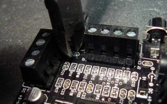
Hi, please see the attached image:
you should see that I've removed C3 and C24, in addition to R3 and R16, and absolutely destroyed C13 and C21, lifting a pad on each. In order to remedy this, note that I have attempted to go directly from the centre pin of the RCA jacks to R8 and R14.
Without an input attached, output terminals display the normal 50 mV or so. However, when I attach an input, output voltage displays just under the full input voltage!
could somebody familiar with these boards (Audio1st seems to have an understanding of the input circuit) please try to explain what's gone wrong? If you need more data, just ask for the photos or measurements you need.
Thankyou for any assistance, I really don't want to have to order another just yet!
Attachments
Hi TheSeekerr:
Basically you are bypassing the DC bias blocking capacitors (C13,C21). Although it can be possible to do this with a TA2024 if your input it's biased similarly, it's not recommended for general use. You should replace those input capacitors (C13,C21) with something like 2.2uF or 3.3uF electrolytics otherwise you risk damaging something. You don't need to connect them to the board necessarily, just break both of those wires you have added and connect them in.
Because the TA2024 doesn't run from an inverting (+ve, GND, -ve) DC supply it uses a +ve DC bias on it's inputs, around which the input signal modulates. C13,C21 stop this draining back into your upstream device, yet allow the incoming AC audio signal through to be amplified.
I hope this is some help (...and correct . )
)
Basically you are bypassing the DC bias blocking capacitors (C13,C21). Although it can be possible to do this with a TA2024 if your input it's biased similarly, it's not recommended for general use. You should replace those input capacitors (C13,C21) with something like 2.2uF or 3.3uF electrolytics otherwise you risk damaging something. You don't need to connect them to the board necessarily, just break both of those wires you have added and connect them in.
Because the TA2024 doesn't run from an inverting (+ve, GND, -ve) DC supply it uses a +ve DC bias on it's inputs, around which the input signal modulates. C13,C21 stop this draining back into your upstream device, yet allow the incoming AC audio signal through to be amplified.
I hope this is some help (...and correct .
)Re: Help! Speaker terminals recieve full input voltage!
Refer to post 61 for a diagram of the input circuit. A capacitor is needed to block DC - one where you have each of your new links. You do not explicitly mention capacitors off board, so this could very well be the problem (i.e. if your source is DC coupled).
Ken
Edit: Oh well - 1 second too late...
TheSeekerr said:Hi, please see the attached image:
could somebody familiar with these boards (Audio1st seems to have an understanding of the input circuit) please try to explain what's gone wrong? If you need more data, just ask for the photos or measurements you need.
Refer to post 61 for a diagram of the input circuit. A capacitor is needed to block DC - one where you have each of your new links. You do not explicitly mention capacitors off board, so this could very well be the problem (i.e. if your source is DC coupled).
Ken
Edit: Oh well - 1 second too late...

Thanks, I was aware of this problem, but didn't think I'd observe the entire voltage at the output......I'll add a pair of 2.2's to it, and see if I can get something sensible out the other end.
You don't need 2.2's- 1uf is plenty.
A 1uf has a -3db point of about 7.5 Hz. What I did was parallel the existing cap with a 1uf- the combination of which has a -3db point of 5.5 Hz.
Making the low end roll off too low allows infrasonic stuff to go through the Tripath-and I'm not too sure how well it handles that stuff.
A 2.2 uf has a -3db point of 3.3 Hz.
Good call on removing C3 and C24. Highs are much improved. Still lacks headroom... Next R8 & R14 change over to 10k Ohm metal oxide resistors... Are 1W flameproof OK?
Also any segestions on soldering on something so small???
Also any segestions on soldering on something so small???
yes, you really need small tips and low power. Too much heat damages components and the pads that they sit upon, so try to keep the heat down. And be careful! 🙄
I personally use a 18W Antex soldering iron with a 0.7mm tip and thin multicore lead/tin solder. Clean up excess solder with a solder pump and desoldering braid, both available cheaply on ebay. Often when you want to remove a component it's worth adding extra solder to it and then dragging the component away from it's pads with the iron when it's hot. Ideally, if you do SMD a lot an SMD hot air/IR rework station is the way to go.
1W resistors seem rather excessive, but they should work. Bear in mind that larger components will likely also have larger self capacitance and inductance however. Metal film 0.25W or less are ideal.
FWIW; I have enjoyed some success removing small SMD components using a sharp pointed X-Acto knife blade. I place the blade tip at the intersection of the chip and board and apply heat to it, sliding the iron down the blade toward the component but not touching it or the board. At some point the adhesion surrenders and the SMD simply "pops up" without damaging the trace.
Hope this helps.
Pete
Hope this helps.
Pete
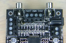
The choice of a 2.2 was mostly dictated by what I had to hand. OK. So, to describe the current setup:
- I removed the quick and dirty hookup wires you can see in the photo
- replace with wire from the centre input terminals to the close side R8 and R14 respectively
- added an outboard pair of RCA jacks, with 2.2uF from the centre pins to the centre inputs.
Methinks this should work, and indeed, I no longer have the huge DC offset problem.....but neither do I have any output. This I do not like. Any more helpful people? (I can post more photos if this isn't a clear enough description)
- Status
- Not open for further replies.
- Home
- Amplifiers
- Class D
- Sure Electronics Tripath boards?