12v DC --> 24v DC 5A SMPS
http://cgi.ebay.com.au/Universal-Ca...photoQQcmdZViewItemQQ_trksidZp1742.m153.l1262
I just picked one of these up from Jaycar (electronics shop here in oz) minus the laptop socket adapters for $20. Will have a play over the weekend and try getting rid of the hiss too.
http://cgi.ebay.com.au/Universal-Ca...photoQQcmdZViewItemQQ_trksidZp1742.m153.l1262
I just picked one of these up from Jaycar (electronics shop here in oz) minus the laptop socket adapters for $20. Will have a play over the weekend and try getting rid of the hiss too.
Hiss
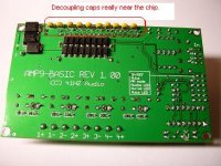
Hi, I've posted in this thread before, but 100nF caps across all hot inputs really near the IC will most likely solve the hiss.....
Look at an AMP9, it's laced with them...
Hi, I've posted in this thread before, but 100nF caps across all hot inputs really near the IC will most likely solve the hiss.....
Look at an AMP9, it's laced with them...
v-bro, Iv'e been hearing you, don't worry. Iv'e got 2 of them amp9-basic kits on the way, and a temperature controlled soldering iron. ;-)
v-bro,
Do you think it would be an idea to simply solder 100nf ceramics to the chip pins on the input side and then to a ground wire? Seems to be quite a bit of room and the pins are thick. Below is a pic of the chip.
http://pix.minirig.org.au/main.php?g2_itemId=276
Do you think it would be an idea to simply solder 100nf ceramics to the chip pins on the input side and then to a ground wire? Seems to be quite a bit of room and the pins are thick. Below is a pic of the chip.
http://pix.minirig.org.au/main.php?g2_itemId=276
Hi, well not only the inputs, what would be more important is the 5V section. I don't have that amp right here, but I'm sure it uses some kind of 5V regulator. It's either on board of the IC or separate.
Most of the times it's a 78L05 or LM317 regulator when it's external...
You can just place these caps without any harm on any lead that has voltage on it. Most important is to do it real close to the IC. When it has a separate 5V regulator than place two caps, one near the regulator and one near where the 5V enters the IC.....
Use 100nF and at least 50V, the inputs can also use two 100pF ceramics to filter on a really high frequency range.....
I'm still pretty sure the hiss is caused by lack of ceramic caps....
voltages on the pins with 24v going in no load
this is the volts on the pins.
http://pix.minirig.org.au/main.php?g2_itemId=279&g2_imageViewsIndex=1
there is no external 5v regulator, must be on the chip.
this is the volts on the pins.
http://pix.minirig.org.au/main.php?g2_itemId=279&g2_imageViewsIndex=1
there is no external 5v regulator, must be on the chip.
Got the amp!
Hello guys,
The amp just arrived (pretty fast, I ordered only a few days ago).
Only checked it briefly. On the first run it played music, but with terrible loud beeps in the background. I figuered out that the cause seems to be the headphone out of my computer, since its running fine from my portable. I'll check later if it runs flawlessly from the regular output of my soundcard (I hope so). 🙁 Any hints regarding this appreciated. 🙂
Regarding the hiss, it's present, but I'll try a few of the fixes postet earlier. I haven't got much time at the moment (girlfriend and finals in school) so it might take a while. 😉
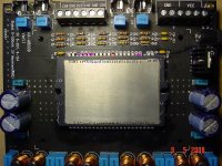
Hi, I put some coloured dot on your pic, red is a must try and purple are also pins to try a cap on, I don't think the outputs really need them.
Just first try the input side of the IC.
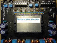
Than also add caps on the input pins, you can beep these pins from the blue input caps(the square ones) with your DMM. The inputs go to the blue caps...than measure between the other pin of each blue cap towards the IC pins.
Than the best would be to solder the cap directly on the IC pins and than to a near ground plane... (or add a ground wire)....
Just first try the input side of the IC.
Than also add caps on the input pins, you can beep these pins from the blue input caps(the square ones) with your DMM. The inputs go to the blue caps...than measure between the other pin of each blue cap towards the IC pins.
Than the best would be to solder the cap directly on the IC pins and than to a near ground plane... (or add a ground wire)....
Attachments
If it doesn't help do the same with the bottom row of pins.....these caps cost practically nothing, so try it and post your experiences for all others here...
You'll be a pioneer! 😎
You'll be a pioneer! 😎
cheers for that, very helpful. Will go get some ceramics. I might do them one by one attaching them to the blue wire using your purple dots as a priority order. If I find one change that makes a dramatic reduction in hiss will report back. Even if I smoke the thing is no biggie as I have 2 amp9-basic on the way ;-)
just before I start with the ceramics. here is a measurement of the hiss. It starts at about 5khz and then rises.
http://pix.minirig.org.au/main.php?g2_itemId=282
http://pix.minirig.org.au/main.php?g2_itemId=282
Tekko said:I´d replace those pesky junk output inductors first thing.
Would you please suggest one or more replacement inductors?
V-bro, Iv'e added 100nF to all the pins you marked red and purple and the 23v ones, doing it one-by-one testing the sound each time. It didn't make any difference at all. Iv'e run out of caps now, work on it will have to continue next week.
A good choice would be a iron powder toroid, a commonly used core with diy class d is the T106-2 from Micrometals.com
Of cource a smaller core can be used for lower power amplifiers, for a 100W amp a T94-2 and maybe even smaller one would work.
Of cource a smaller core can be used for lower power amplifiers, for a 100W amp a T94-2 and maybe even smaller one would work.
so get some of those cores, wrap about 20 wraps of copper wire and replace the inductors on board is your suggestion?
Inductors can be found on RS-components, Panasonic makes nice ones.
Probably will take some PCB modding or wire routing though...
If I have some time I'll look 'em up...
Pity that you haven't had any progress with the caps Col.... But I still think it's a matter of decoupling the right pins.....
Probably will take some PCB modding or wire routing though...
If I have some time I'll look 'em up...
Pity that you haven't had any progress with the caps Col.... But I still think it's a matter of decoupling the right pins.....
- Status
- Not open for further replies.
- Home
- Amplifiers
- Class D
- Sure-Electronics.com class d amps