Lambda JWS300 24v 14A SMPS
I just picked up 4 x new Lambda JWS300 24v 14A SMPS for AUD$50! 🙂 Have been testing with my Sure-Electronics 4*100w most of the day. Sounding awesome, better than the Meanwell even. Looks like I have a few more amplifiers to build 😀 more later.
I just picked up 4 x new Lambda JWS300 24v 14A SMPS for AUD$50! 🙂 Have been testing with my Sure-Electronics 4*100w most of the day. Sounding awesome, better than the Meanwell even. Looks like I have a few more amplifiers to build 😀 more later.
fredos said:Anybody blow a module yet? We torture them a lot and just blow a power supply from now...
Fredos
Yep...dunno how either lol... I did short the output to +12V...but that was a month before it failed. Oh well it was worth the $40 or so.
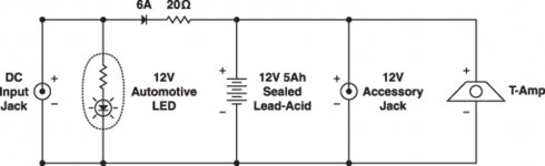
If you check the podzuma schematics, he charges his 12v battery pack with a diode and resistor.
Now, I have 2 12v 7.5ah batteries in series for this amp. If I put 2 12v accessory jacks in series, what kind of things do I need to change in order to charge my 24v battery pack instead of this 12v circuit.
Max
Now, I have 2 12v 7.5ah batteries in series for this amp. If I put 2 12v accessory jacks in series, what kind of things do I need to change in order to charge my 24v battery pack instead of this 12v circuit.
Max
Attachments
This was listed as being a suitable attenuation of the hiss/white noise on the amp on page 7 by sharpi:
"1. replace 1uF bypasses on power pins with 0.22uF ceramic (from an old 41hz kit)
2. add 300pF silver mica from each input to ground
3. add a thick earth cable from chassis ground to amp 0V connection (as well as 0V from smps) and also to both audio grounds"
Are those all 35v or some other voltage?
And has anyone else tried those mods to get a similar result for this amp?
I have a 2 channel coming and I am gearing up for ideas and work ahead.
You left out this part of that post:
"This made a significant difference to the hiss level, although I can't say what was most beneficial as I did all changes at once!"
http://www.diyaudio.com/forums/showthread.php?postid=1373646#post1373646
"This made a significant difference to the hiss level, although I can't say what was most beneficial as I did all changes at once!"
http://www.diyaudio.com/forums/showthread.php?postid=1373646#post1373646
Using 4-channel module as a balanced stereo amp
Hello,
I'm thinking about getting one of the 4-channel modules. Since I got a source with balanced outputs it would be good to have a balanced amplifier as well.
Thus my question is if I can use the 4-channel amp balanced.
Can I just feed one channel with the hot signal and the other with the cold signal?
Do I have to join the signals or can I just connect hot to the positive speaker out and cold to the negative one?
And what to do with the ground?
Sorry for the possibly stupid questions, I'm quite new to DIY electronics. 🙂
Stop wasting your time...
I must admit I read through the thread a bit fast, but the hiss that people experience may well be caused by the lack of filtering on the auxiliary voltage and IC outputs. A good design is loaded with 100nF caps to ground really near the IC or regulator.
I was also never really charmed by those type of inductors, they are really poorly shielded (the ends radiate a lot! Even at this frequency)
Stop wasting time on this design and get a decent AMP9 or even an MC4x100 from audiodigit is better....
Or get two of those nice price Clarity modules if you want quality..
http://www.elektor.com/products/kits-modules/modules/clarity-eindversterker-(030217-91).91408.lynkx
My personal favorite is 41hz.....
Re: Using 4-channel module as a balanced stereo amp
Unfortunately that won't work well since the amplifier is already a full-bridge design on each channel.
You'd probably be better off with an amplifier that has a real balanced input, such as the UCDs. Quite a bit more expensive but definitely worth it.
Else you could just connect the return line to the amplifier ground, and the hot to the input. I've seen two different ways to do it, some people connect the cable shield to the return wire at the amplifier end, some people leave it floating. Which is better? I haven't got a clue, never compared it.
Möter said:Can I just feed one channel with the hot signal and the other with the cold signal?
Do I have to join the signals or can I just connect hot to the positive speaker out and cold to the negative one?
And what to do with the ground?
Unfortunately that won't work well since the amplifier is already a full-bridge design on each channel.
You'd probably be better off with an amplifier that has a real balanced input, such as the UCDs. Quite a bit more expensive but definitely worth it.
Else you could just connect the return line to the amplifier ground, and the hot to the input. I've seen two different ways to do it, some people connect the cable shield to the return wire at the amplifier end, some people leave it floating. Which is better? I haven't got a clue, never compared it.
Möter, if you are new to DIY electronics the Sure Electronics 4*100w is a great amp project, it's dirt cheap and easy to implement and what the heck if you smoke it at least it won't hurt your wallet 😉 I learned heaps building mine. Get it with one of the Meanwell 24v 14.6A switch mode power supplies.
Re: Re: Using 4-channel module as a balanced stereo amp
Thanks for your answers TheMG, col.
I will get one of the 4-channel amps together with the SMPS for just the reason that it is so cheap, just as you said, col.
I'm planning to get a pair of UcD180s sooner or later, but before I do this I'm going to teach myself a bit of electronics in order to minimise the risk of ruining them. 😉
By return line, you probably mean the cold end, do you?Originally posted by TheMG Unfortunately that won't work well since the amplifier is already a full-bridge design on each channel.
[...]
Else you could just connect the return line to the amplifier ground, and the hot to the input.
Thanks for your answers TheMG, col.
I will get one of the 4-channel amps together with the SMPS for just the reason that it is so cheap, just as you said, col.
I'm planning to get a pair of UcD180s sooner or later, but before I do this I'm going to teach myself a bit of electronics in order to minimise the risk of ruining them.
If you download a behringer manual (http://www.behringerdownload.de/CX2310/CX2310_ENG_Rev_A.pdf) will do and look somewhere near the back it will have a diagram of how to wire a balanced/unbalanced cable. I think it is basically bridging pin 1 and 3. There is a good diagram of an alternative way of doing it on the hypex site http://www.hypex.nl/docs/wiring.pdf I have cables that are done both ways but can't tell the difference.
The sure electronics 4*100w was my first amp build and then I moved onto building a UcD180. You can see pictures on my website.
😀
Thanks for the links, but I already read through the Hypex docs, but the pics on your website are really nice and helpful.
On these pics I see that you connected the SMPS to the amp with one cable for +V and one for -V only, but on the SMPS and the amp there are 3 connectors each. I also saw someone wiring the amp with two cables each in this thread.
Which is the right way to do it if there even is one?
On these pics I see that you connected the SMPS to the amp with one cable for +V and one for -V only, but on the SMPS and the amp there are 3 connectors each. I also saw someone wiring the amp with two cables each in this thread.
Which is the right way to do it if there even is one?
Ouroboros: I bet it was the 300pF caps on each input to ground that had the most effect!
I'm going to give this a try, have ordered some 300pf mica. Would be great to get this amp hiss free or dramatically reduced, I would consider buying a couple more then.
Hmmm, I only have some 220pF and 470pF ceramics kicking around. I might give those a try.
Also the 220nF bypasses, those I have.
Also the 220nF bypasses, those I have.
Has anyone figured out the zobel thing. I've done some reading and I'm more confused than ever. A 1/2 Watt resistor makes no sense to me. From my reading the ratio is 10:1 100W power out equals a 10W zobel resistor.
MikeHunt79 is that how you calculated your resistors based on 65W out? (probably should have asked this in a separate post, lazy)
Oh,ya! What's with the cling wrap on your work surface.? 😉
There's a new thread on the subject:
http://www.diyaudio.com/forums/showthread.php?threadid=120028
MikeHunt79 is that how you calculated your resistors based on 65W out? (probably should have asked this in a separate post, lazy)
Oh,ya! What's with the cling wrap on your work surface.? 😉
There's a new thread on the subject:
http://www.diyaudio.com/forums/showthread.php?threadid=120028
Bob_Sled said:MikeHunt79 is that how you calculated your resistors based on 65W out? (probably should have asked this in a separate post, lazy)
Oh,ya! What's with the cling wrap on your work surface.? 😉
Nothing sinister, 😉 I use it to smear around thermal compound. I wrap cling film on my finger, then apply it to the heatsink of whatever I'm making...
As for the resistors, I just used what I had handy, they are a big on the large side, but they stay a lot cooler than the original zobels when you turn up the volume....

I think I used 1w resistors for my zobels. I have also been driving the amp very hard and they have not smoked yet. Here is a pic of my zobels:
http://www.minihub.org/~colren/speakahs/minirig-sureelectronics/6.html
http://www.minihub.org/~colren/speakahs/minirig-sureelectronics/6.html
Also, my 300pF caps arrived in the post, so will have a go at reducing the white noise soon, hope it works, otherwise i'm off to 41hz to get a amp9 
- Status
- Not open for further replies.
- Home
- Amplifiers
- Class D
- Sure-Electronics.com class d amps